3. Lab Tasks
3.1. Day 1 tasks
In Day 1's lab, attendee will learn how to onboard virtual Edge router CSR1kv into the SDWAN fabric, and how to create device template using feature template for basic SDWAN features.
Similar to real world scenario, for SDWAN deployment, the first step is to install controllers. It is common to use Cisco hosted controller. The Cisco CloudOps team will take care of the controller design and installation. Attendee can reference the Cisco SD-WAN CloudOps document for detail information.
https://www.cisco.com/c/en/us/td/docs/routers/sdwan/knowledge-base/CloudOps/b-cisco-sdwan-cloudops.html Another controller deployment model is on-premise controller. Attendee can reference the SDWAN getting started guide for controller installation. https://www.cisco.com/c/en/us/td/docs/routers/sdwan/configuration/sdwan-xe-gs-book/cisco-sd-wan-overlay-network-bringup.html In this lab, all SDWAN controllers including vManage, vSmart and vBond are pre-configured for each pod.After controllers are up, the next step is to bring up the headend or datacenter. The headend or datacenter will function as transit site between SDWAN and non SDWAN site. In this lab, DC WAN Edges are pre-configured and onboarded to SDWAN fabric. Attendee needs to review the SDWAN basic template configuration and verify connectivity. To make the DC as transit site between SDWAN and non SDWAN, attendee needs to configure the WAN Edge router to establish OSPF neighbor with DC Router and redistribute the OSPF learned routes into OMP.
3.1.1. Verify DC connectivity
In this task, attendee will verify reachability from DC to remote site1 and site2. Reference Device access table for login IP and credential.
- Step1 SSH into DC1-WAN-Agg and verify it has BGP neighbor with the MPLS PE, and also learns other site prefixes over BGP.
Run
show ip bgp summary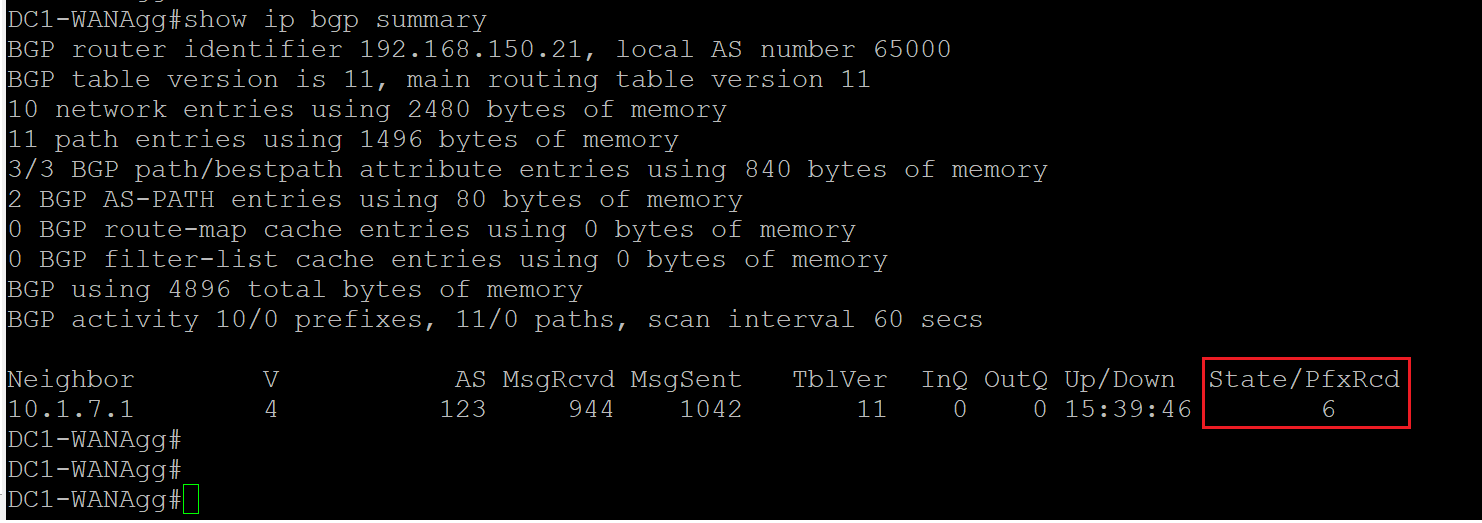
Run show ip route bgp
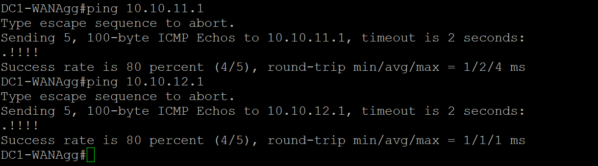
 - Step2 Verify reachability to dc1-cedge1 and dc1-cedge2
Run
- Step2 Verify reachability to dc1-cedge1 and dc1-cedge2
Run ping 10.10.11.1 and ping 10.10.12.1
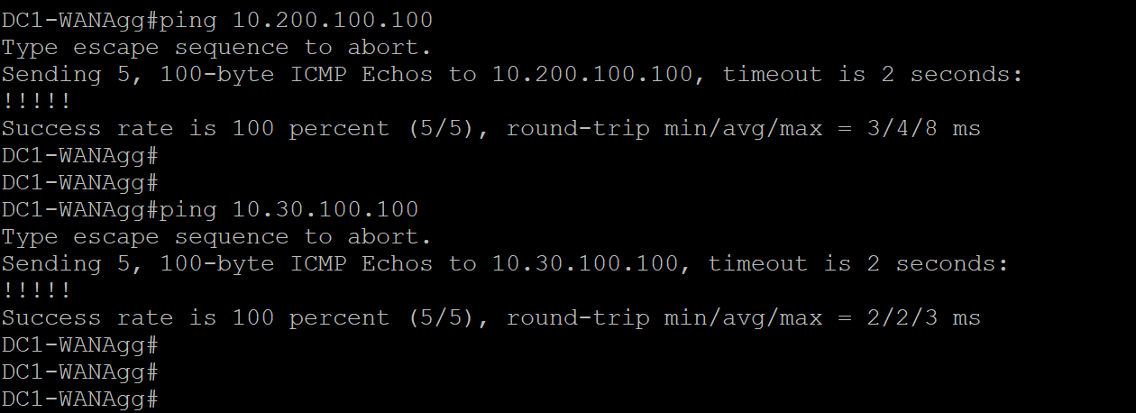
 - Step3 Verify reachability to Site1-VM1 and site2-VM1
Run
- Step3 Verify reachability to Site1-VM1 and site2-VM1
Run ping 10.200.100.100, ping 10.30.100.100
3.1.2. vManage walk through
In this task, attendee will walk through the vManage GUI.
-
Step1 Login vManage from https://198.18.133.200:8443
Note Please ignore the self sign cert warning and proceed. Login to vManage using admin/pocadmin for username/password, then click Log In.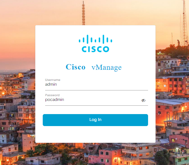
-
Step2 On the main dashboard, verify the SUMMARY panel for quick overview of the fabric inventory; verify Control Status for overview of control channels.

-
Step3 Navigate to the panel on the left and click Monitor - Network for detail information of each device in the fabric.
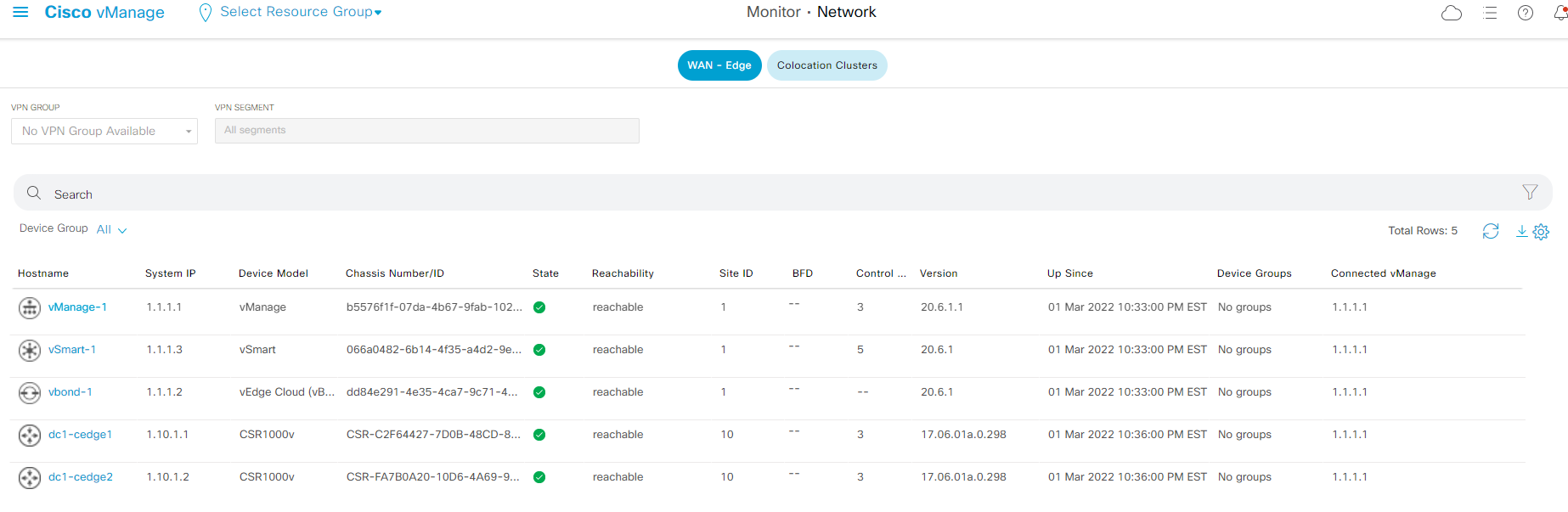
-
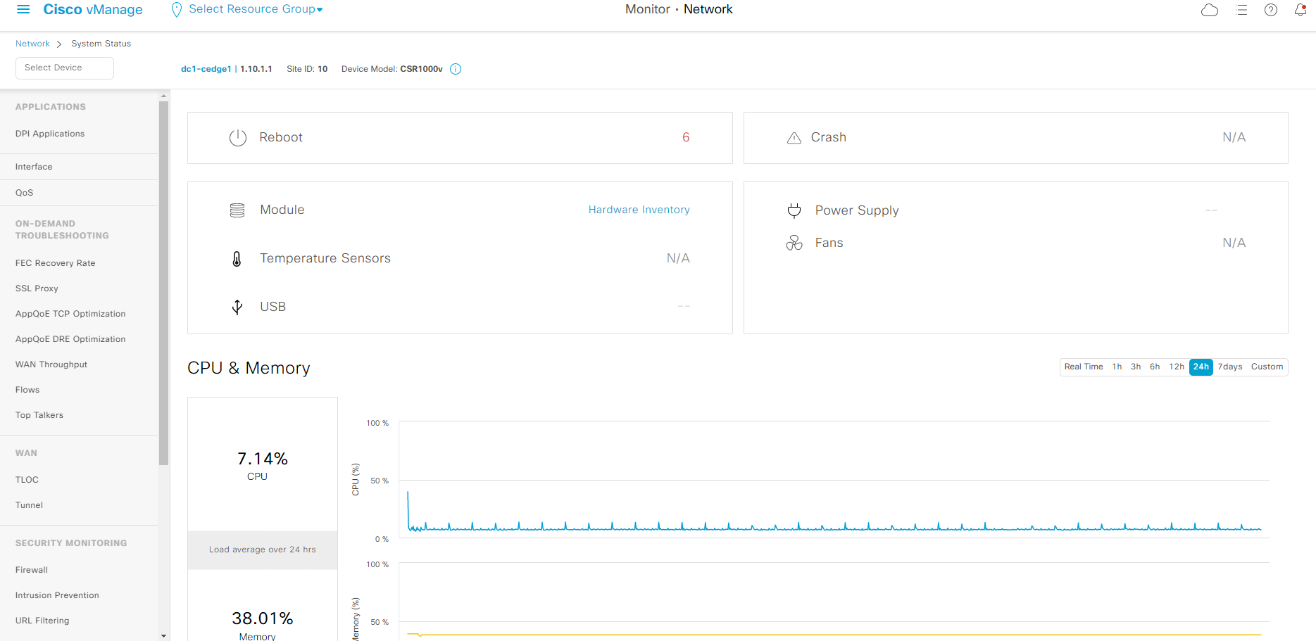
Step4 click device name dc1-cedge1 to access the device specific information. This is main page to verify device information, statistics, and troubleshooting options. Explore the page and get familiar with navigation panel on the left such as supported troubleshooting capability, commands available from Real Time.
- Step5 Navigate to the panel on the left and click Configuration - Certificates for the WAN Edge and Controllers certificate status.
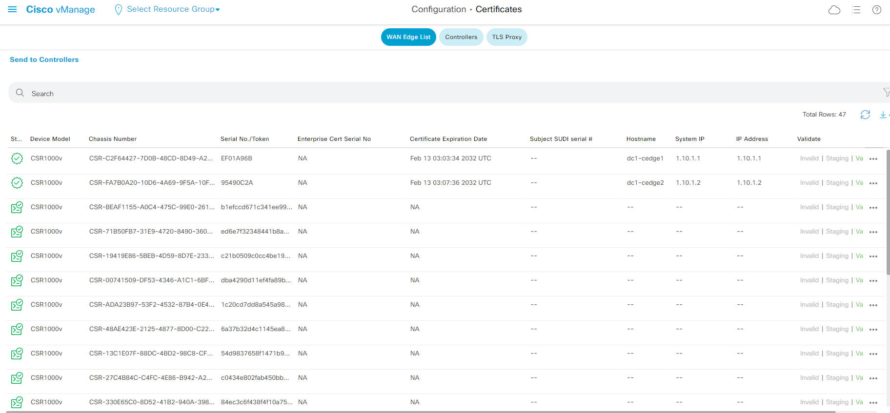
On the WAN Edge List certificate page, pay attention to the state of the certificate, chassis number as well as Serial No/Token. Attendee will use information on this page to onboard virtual WAN Edge in this lab.
- Step6 Navigate to the panel on the left and click Tools - SSH Terminal for the build in device access tool.
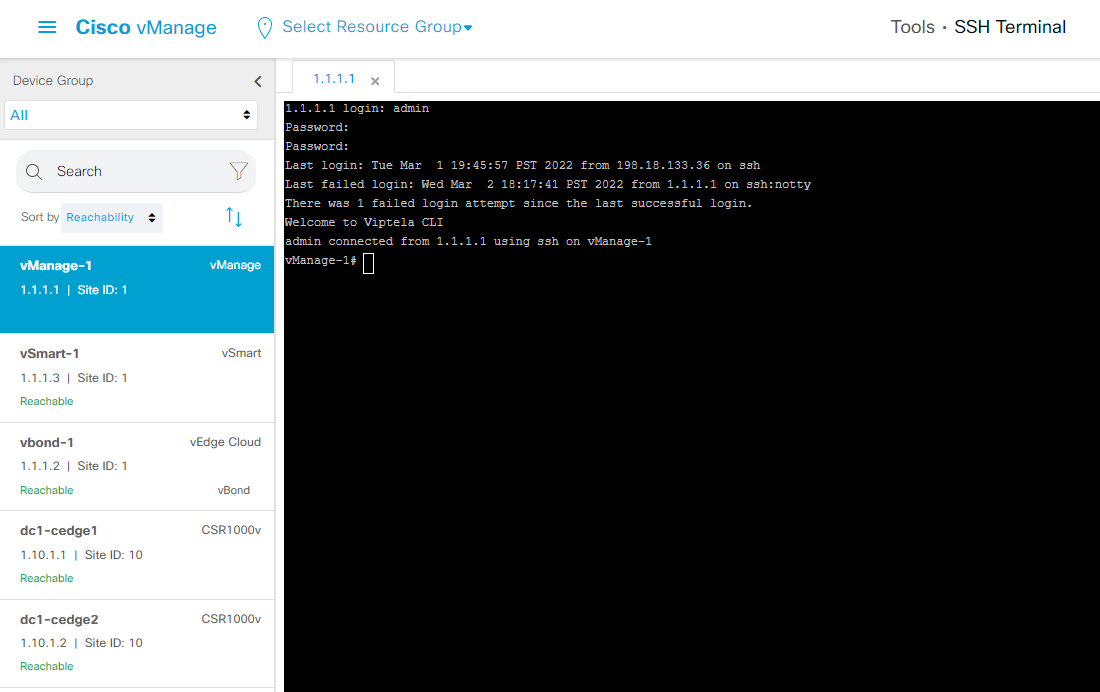
Feel free to explore other operations on vManage portal.
3.1.3. Review DC Edge Device Templates
In this task, attendee will review the pre-configured device templates for dc1-cedge1 and dc1-cedge2.
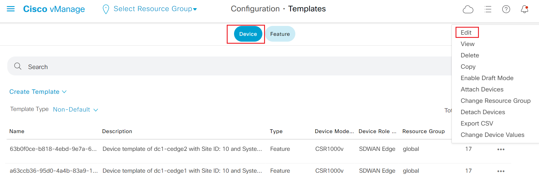
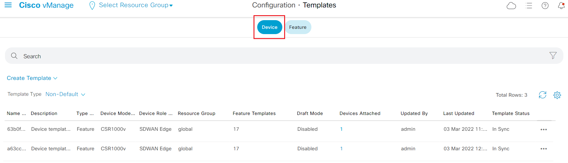
- Step1 Navigate to the panel on the left and click Configuration - Templates for the device and feature template.
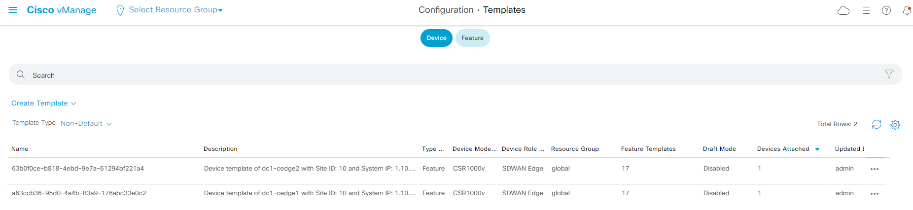
- Attendee should see two prebuilt device templates as shown in the screenshot above.
- Step2 Locate one of the device template and click the '...' on the right and select Edit to view the template configuration
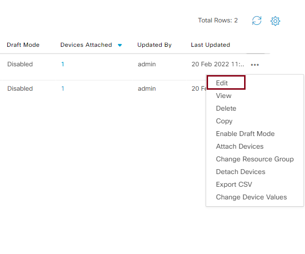
- This will list all feature templates associated to the device template. You can click each feature template and select View Template to view the configuration of the feature template.
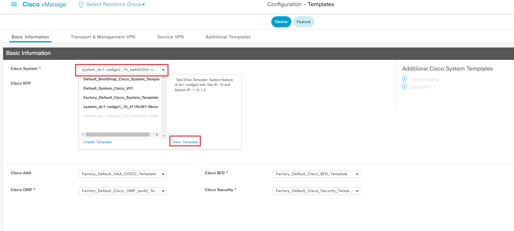
A device template consists of few sections, each section has it own set of feature templates. The mandatory feature templates are marked as '*'.
3.1.4. Add OSPF to DC Device Template
In this section, attendee will modify the pre-configured device template and add OSPF as routing protocol for service side VPN. After configuring OSPF, attendee will verify OSPF neighbor with dc-wan-agg router.
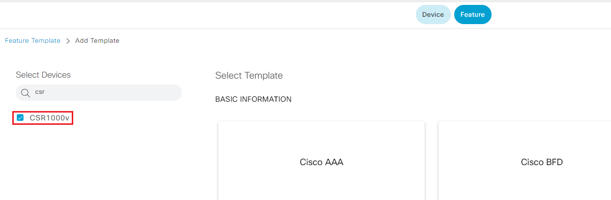
- Step1 Navigate to the panel on the left and click Configuration - Templates, then click Feature tab on the top to switch to the feature template configuration.

- Step2 Click Add Template, find and select CSR 1000v under select Devices
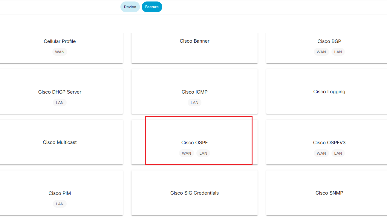
- Step3 Find and select Cisco OSPF template on the right
-
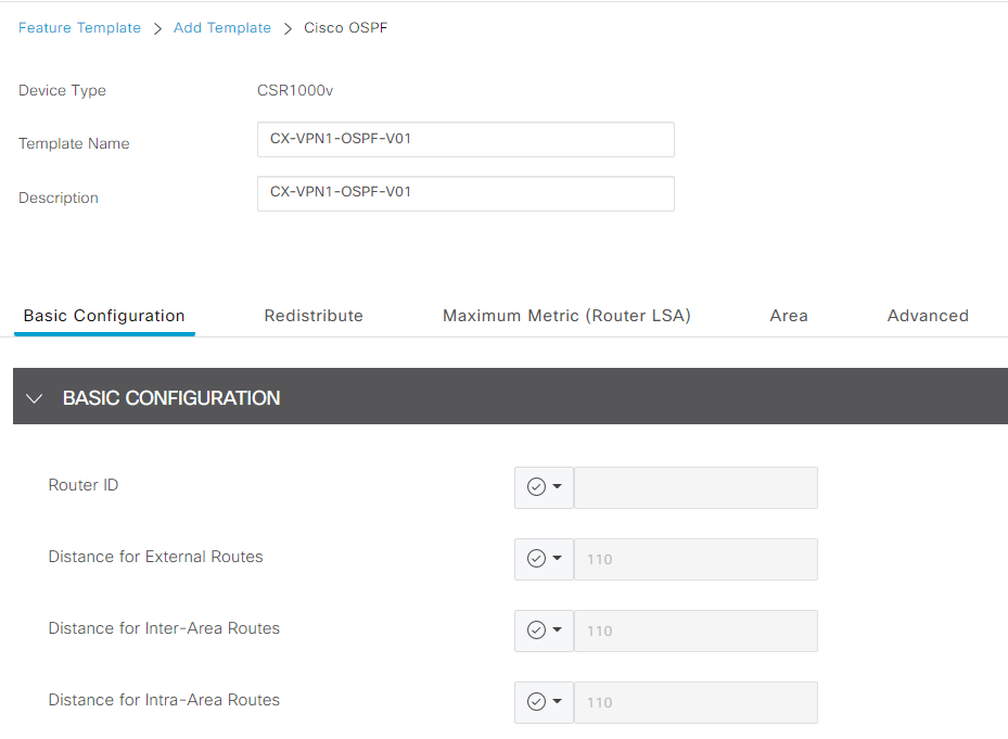
Step4 Create OSPF template with following name and description. Leave BASIC CONFIGURATION as the default.
- Template Name|CX-VPN1-OSPF-V01|
- Description|CX-VPN1-OSPF-V01|
-
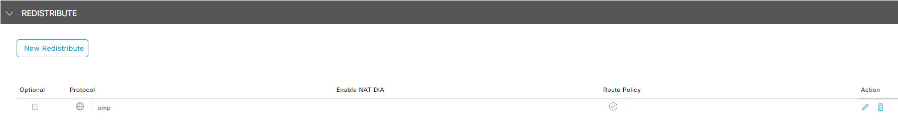
Click New Redistribute under REDISTRIBUTE section, select omp from protocol drop down list then click Add Note In the lab, we will not add Route Policy, but in production deployment it's good practice to use route policy to tag routes being redistributed from OMP into OSPF
- Click New Area under AREA section, enter 100 in Area Number, click + Add Interface to add interface that participants in OSPF process
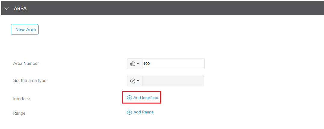
- Click Add Interface from the popup window for Interface configuration
- Click the drop down for Interface Name, move your mouse to Device Specific, enter VPN1_OSPF_INT as variable for OSPF Interface Name
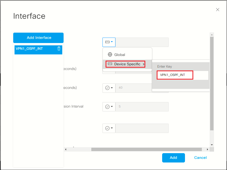
- Explore other OSPF configuration options but for lab leave other filed as default and click Add to add the interface variable for OSPF area 100.
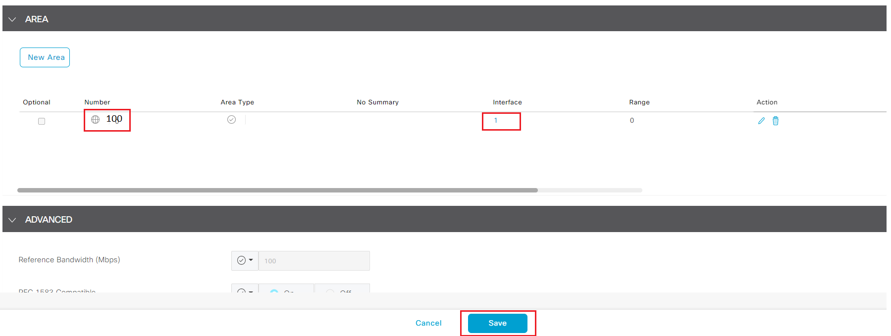
- Click Add to add OSPF Area config
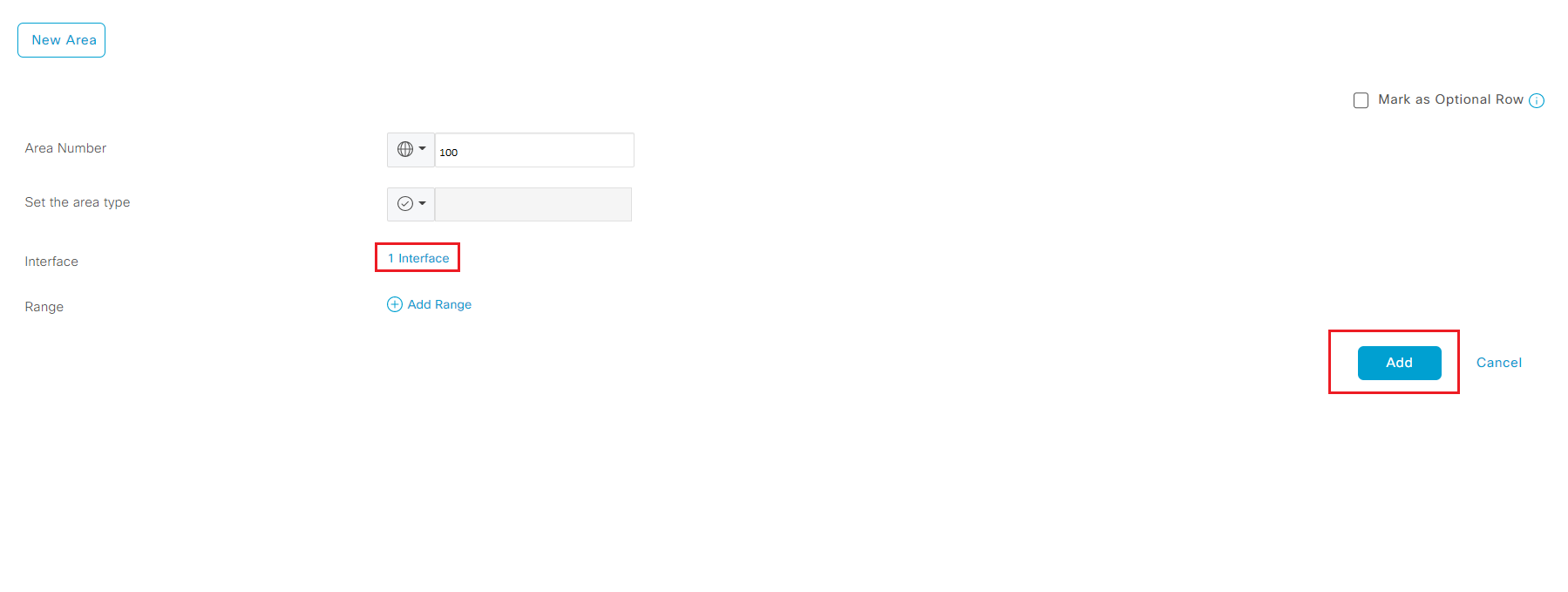
- Leave other field as default and click Save to finish configuring OSPF feature template
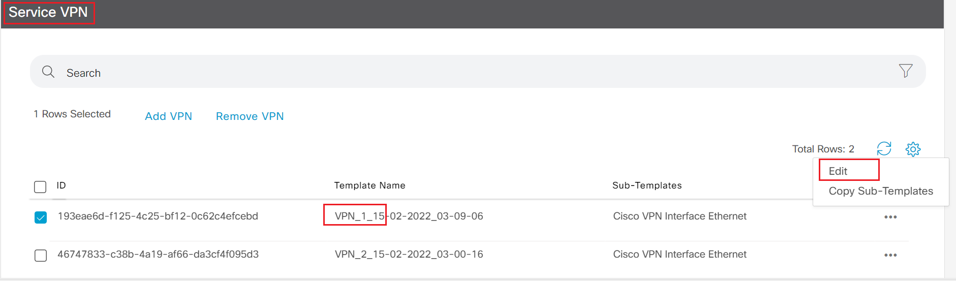
- Step5 Click Device on the top to switch to device template. Locate one of the device template and click the '...' on the right and select Edit to add new OSPF template to pre-configured DC device template.
- Step6 Move to Service VPN section, highlight the template of VPN_1 click the ... and select Edit
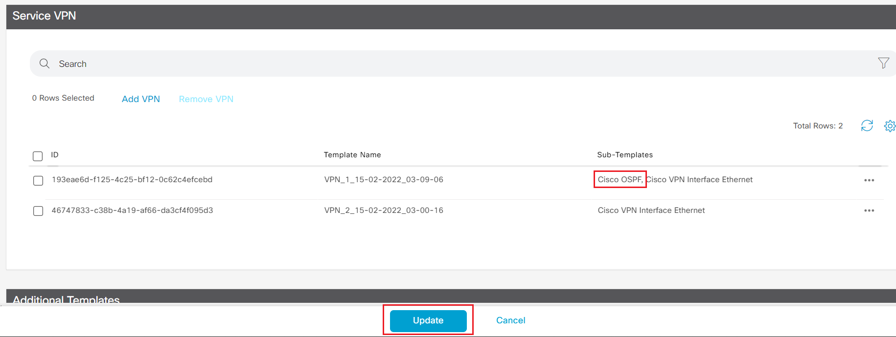
- Step7 Select Cisco OSPF from the Additional Cisco VPN Templates panel on the right. Select CX-VPN1-OSPF-V01 from the drop down list for Cisco OSPF template.

-
Step8 Click Save to return back to device template and click Update to update the device template.
Note Changing device template will trigger configuration update for device attached to the device template. In production network, it is common practice to replicate the existing device template, modify on the new device template then associate device to the new device template.
- Step9 Click the ... to update device configuration. Enter GigabitEthernet3 in the field for new variable you just created in OSPF teamplte.
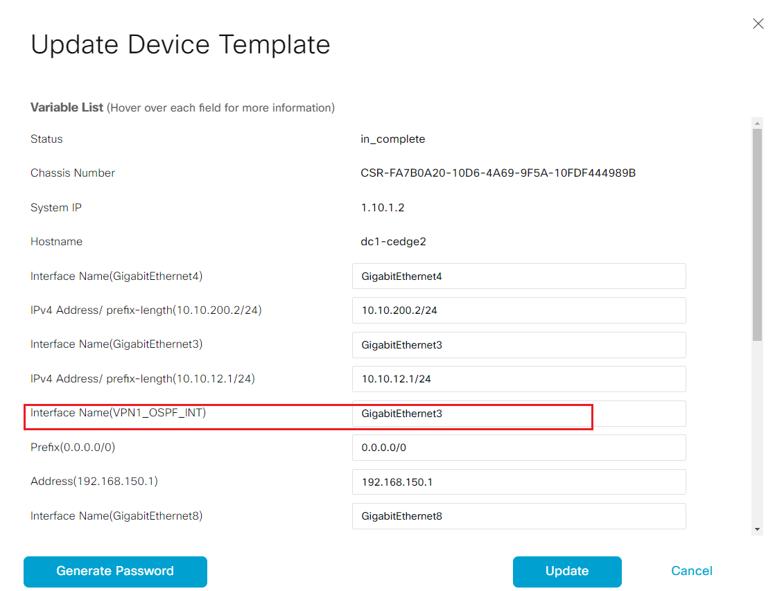
-
Step10 Click Update to save the change, and click Next to the configuration preview
-
Step11 click the device name on the left panel, then click Config Diff to do a configuration Side by Side comparison
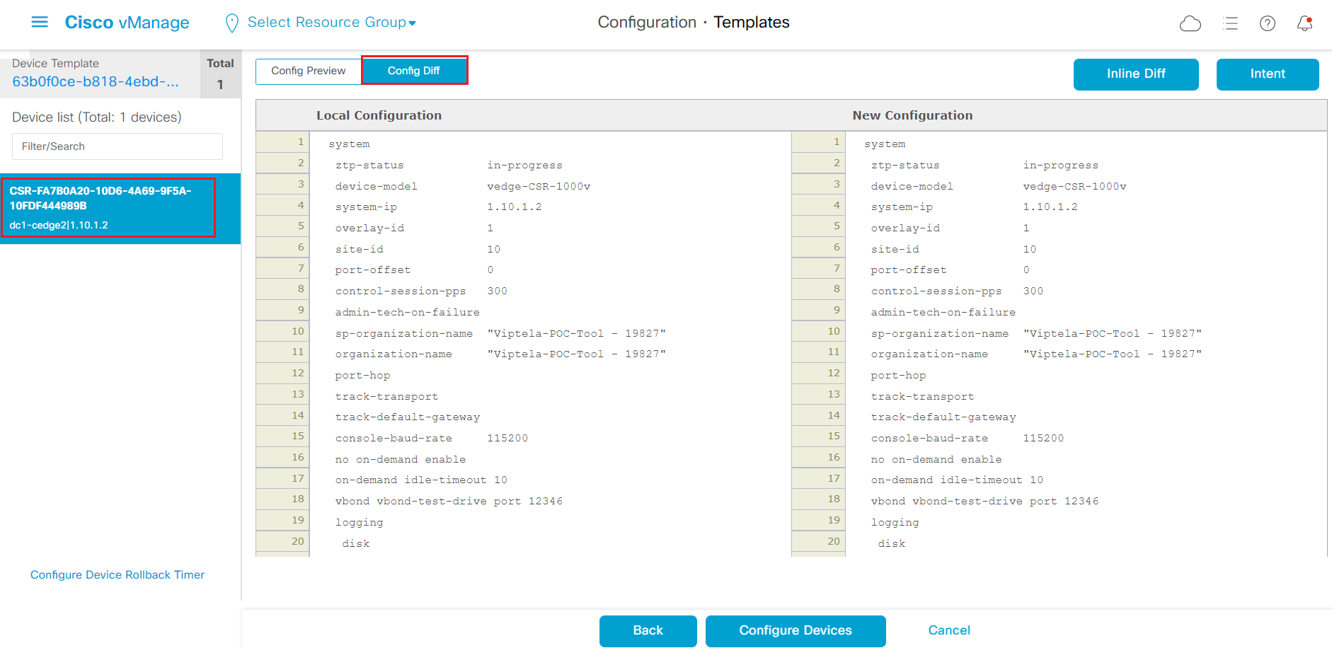
-
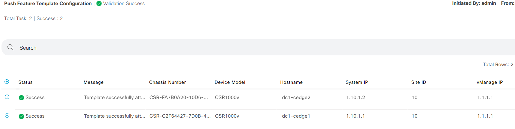
Step12 After reviewing the new configuration change, click Configure Devices to push the configuration.
-
Step13 Wait for the configuration push is successfully finished. Repeat the same above steps to add OSPF on the other pre-configured DC device template.
-
Step14 Login to dc1-wan-agg, and run
show ip ospf neighbor
 DC1-WANAgg#show ip ospf neighbor

Neighbor ID     Pri   State           Dead Time   Address         Interface
10.10.12.1        1   FULL/BDR        00:00:33    10.10.12.1      GigabitEthernet2
10.10.11.1        1   FULL/BDR        00:00:32    10.10.11.1      GigabitEthernet1
DC1-WANAgg#
- login to dc1-cedge1 and run
show ip route vrf 1
dc1-cedge1#show ip route vrf 1

Routing Table: 1
Codes: L - local, C - connected, S - static, R - RIP, M - mobile, B - BGP
       D - EIGRP, EX - EIGRP external, O - OSPF, IA - OSPF inter area
       N1 - OSPF NSSA external type 1, N2 - OSPF NSSA external type 2
       E1 - OSPF external type 1, E2 - OSPF external type 2, m - OMP
       n - NAT, Ni - NAT inside, No - NAT outside, Nd - NAT DIA
       i - IS-IS, su - IS-IS summary, L1 - IS-IS level-1, L2 - IS-IS level-2
       ia - IS-IS inter area, * - candidate default, U - per-user static route
       H - NHRP, G - NHRP registered, g - NHRP registration summary
       o - ODR, P - periodic downloaded static route, l - LISP
       a - application route
       + - replicated route, % - next hop override, p - overrides from PfR
       & - replicated local route overrides by connected

Gateway of last resort is not set

      10.0.0.0/8 is variably subnetted, 9 subnets, 2 masks
O E2     10.1.11.0/24 [110/1] via 10.10.11.2, 07:48:43, GigabitEthernet3
O E2     10.1.12.0/24 [110/1] via 10.10.11.2, 07:48:43, GigabitEthernet3
C        10.10.11.0/24 is directly connected, GigabitEthernet3
L        10.10.11.1/32 is directly connected, GigabitEthernet3
O        10.10.12.0/24 [110/2] via 10.10.11.2, 07:48:43, GigabitEthernet3
O        10.10.100.0/24 [110/2] via 10.10.11.2, 07:48:43, GigabitEthernet3
O E2     10.30.100.0/24 [110/1] via 10.10.11.2, 07:48:43, GigabitEthernet3
O E2     10.200.100.0/24 [110/1] via 10.10.11.2, 07:48:43, GigabitEthernet3
O E2     10.200.200.0/24 [110/1] via 10.10.11.2, 07:48:43, GigabitEthernet3
- login to dc1-cedge2 and run
show ip route vrf 1
dc1-cedge2#show ip route vrf 1

Routing Table: 1
Codes: L - local, C - connected, S - static, R - RIP, M - mobile, B - BGP
       D - EIGRP, EX - EIGRP external, O - OSPF, IA - OSPF inter area
       N1 - OSPF NSSA external type 1, N2 - OSPF NSSA external type 2
       E1 - OSPF external type 1, E2 - OSPF external type 2, m - OMP
       n - NAT, Ni - NAT inside, No - NAT outside, Nd - NAT DIA
       i - IS-IS, su - IS-IS summary, L1 - IS-IS level-1, L2 - IS-IS level-2
       ia - IS-IS inter area, * - candidate default, U - per-user static route
       H - NHRP, G - NHRP registered, g - NHRP registration summary
       o - ODR, P - periodic downloaded static route, l - LISP
       a - application route
       + - replicated route, % - next hop override, p - overrides from PfR
       & - replicated local route overrides by connected

Gateway of last resort is not set

      10.0.0.0/8 is variably subnetted, 9 subnets, 2 masks
O E2     10.1.11.0/24 [110/1] via 10.10.12.2, 07:53:41, GigabitEthernet3
O E2     10.1.12.0/24 [110/1] via 10.10.12.2, 07:53:41, GigabitEthernet3
O        10.10.11.0/24 [110/2] via 10.10.12.2, 07:53:41, GigabitEthernet3
C        10.10.12.0/24 is directly connected, GigabitEthernet3
L        10.10.12.1/32 is directly connected, GigabitEthernet3
O        10.10.100.0/24 [110/2] via 10.10.12.2, 07:53:41, GigabitEthernet3
O E2     10.30.100.0/24 [110/1] via 10.10.12.2, 07:53:41, GigabitEthernet3
O E2     10.200.100.0/24 [110/1] via 10.10.12.2, 07:53:41, GigabitEthernet3
O E2     10.200.200.0/24 [110/1] via 10.10.12.2, 07:53:41, GigabitEthernet3
dc1-cedge2#
Other site prefixes "10.30.100.0/24","10.200.100.0/24" and "10.200.200.0/24" are learned on edge routers.
3.1.5. Verify network prefixes in fabric
In this task, attendee will learn how to verify OMP route in fabric, and also learn how to advertise routes into OMP.
- Step1 Login to vSmart-1 and run
show omp route vpn 1 | t
vSmart-1# show omp route vpn 1
Code:
C   -> chosen
I   -> installed
Red -> redistributed
Rej -> rejected
L   -> looped
R   -> resolved
S   -> stale
Ext -> extranet
Inv -> invalid
Stg -> staged
IA  -> On-demand inactive
U   -> TLOC unresolved

                                            PATH                      ATTRIBUTE
VPN    PREFIX              FROM PEER        ID     LABEL    STATUS    TYPE       TLOC IP          COLOR            ENCAP  PREFERENCE
--------------------------------------------------------------------------------------------------------------------------------------
1      10.10.11.0/24       1.10.1.1         66     1003     C,R       installed  1.10.1.1         mpls             ipsec  -
                           1.10.1.1         68     1003     C,R       installed  1.10.1.1         biz-internet     ipsec  -
                           1.10.1.2         66     1003     R         installed  1.10.1.2         mpls             ipsec  -
                           1.10.1.2         68     1003     R         installed  1.10.1.2         biz-internet     ipsec  -
1      10.10.12.0/24       1.10.1.1         66     1003     R         installed  1.10.1.1         mpls             ipsec  -
                           1.10.1.1         68     1003     R         installed  1.10.1.1         biz-internet     ipsec  -
                           1.10.1.2         66     1003     C,R       installed  1.10.1.2         mpls             ipsec  -
                           1.10.1.2         68     1003     C,R       installed  1.10.1.2         biz-internet     ipsec  -
1      10.10.100.0/24      1.10.1.1         66     1003     C,R       installed  1.10.1.1         mpls             ipsec  -
                           1.10.1.1         68     1003     C,R       installed  1.10.1.1         biz-internet     ipsec  -
                           1.10.1.2         66     1003     C,R       installed  1.10.1.2         mpls             ipsec  -
                           1.10.1.2         68     1003     C,R       installed  1.10.1.2         biz-internet     ipsec  -
You notice the other site prefixes "10.30.100.0/24","10.200.100.0/24" and "10.200.200.0/24" are not showing up on vSmart. In order to pass the prefixes to the fabric, attendee needs to advertise OSPF routes into OMP.
-
Step2 Login vManage from https://198.18.133.200:8443. Navigate to the panel on the left and click Configuration - Templates, then click Feature tab on the top to switch to the feature template configuration.
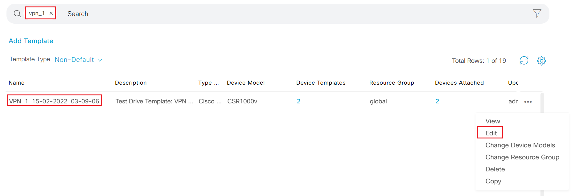
-
Step3 search vpn_1 in the search box; locate the VPN template, click ... and select Edit
-
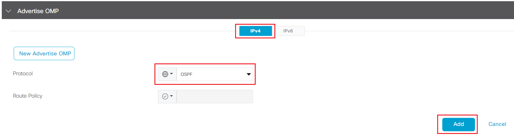
Step4 Click New Advertise OMP under Advertise OMP section
-
Step5 Select OSPF from the Protocol drop down list and click Add
-
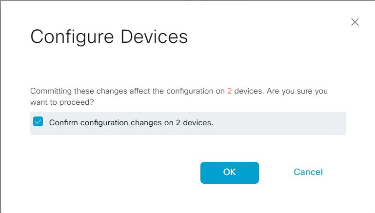
Step6 Click Update - Next - Configure Devices to trigger the configuration push
-
Step7 Click the check box to confirm change on 2 devices
- Step8 Wait after the configuration push is complete successfully
- Step9 Login to vSmart-1 and run
show omp route vpn 1
vSmart-1# show omp route vpn 1
Code:
C   -> chosen
I   -> installed
Red -> redistributed
Rej -> rejected
L   -> looped
R   -> resolved
S   -> stale
Ext -> extranet
Inv -> invalid
Stg -> staged
IA  -> On-demand inactive
U   -> TLOC unresolved

                                            PATH                      ATTRIBUTE
VPN    PREFIX              FROM PEER        ID     LABEL    STATUS    TYPE       TLOC IP          COLOR            ENCAP  PREFERENCE
--------------------------------------------------------------------------------------------------------------------------------------
1      10.1.11.0/24        1.10.1.1         66     1003     C,R       installed  1.10.1.1         mpls             ipsec  -
                           1.10.1.1         68     1003     C,R       installed  1.10.1.1         biz-internet     ipsec  -
                           1.10.1.2         66     1003     C,R       installed  1.10.1.2         mpls             ipsec  -
                           1.10.1.2         68     1003     C,R       installed  1.10.1.2         biz-internet     ipsec  -
1      10.1.12.0/24        1.10.1.1         66     1003     C,R       installed  1.10.1.1         mpls             ipsec  -
                           1.10.1.1         68     1003     C,R       installed  1.10.1.1         biz-internet     ipsec  -
                           1.10.1.2         66     1003     C,R       installed  1.10.1.2         mpls             ipsec  -
                           1.10.1.2         68     1003     C,R       installed  1.10.1.2         biz-internet     ipsec  -
1      10.10.11.0/24       1.10.1.1         66     1003     C,R       installed  1.10.1.1         mpls             ipsec  -
                           1.10.1.1         68     1003     C,R       installed  1.10.1.1         biz-internet     ipsec  -
                           1.10.1.2         66     1003     R         installed  1.10.1.2         mpls             ipsec  -
                           1.10.1.2         68     1003     R         installed  1.10.1.2         biz-internet     ipsec  -
1      10.10.12.0/24       1.10.1.1         66     1003     R         installed  1.10.1.1         mpls             ipsec  -
                           1.10.1.1         68     1003     R         installed  1.10.1.1         biz-internet     ipsec  -
                           1.10.1.2         66     1003     C,R       installed  1.10.1.2         mpls             ipsec  -
                           1.10.1.2         68     1003     C,R       installed  1.10.1.2         biz-internet     ipsec  -
1      10.10.100.0/24      1.10.1.1         66     1003     C,R       installed  1.10.1.1         mpls             ipsec  -
                           1.10.1.1         68     1003     C,R       installed  1.10.1.1         biz-internet     ipsec  -
                           1.10.1.2         66     1003     C,R       installed  1.10.1.2         mpls             ipsec  -
                           1.10.1.2         68     1003     C,R       installed  1.10.1.2         biz-internet     ipsec  -
1      10.30.100.0/24      1.10.1.1         66     1003     C,R       installed  1.10.1.1         mpls             ipsec  -
                           1.10.1.1         68     1003     C,R       installed  1.10.1.1         biz-internet     ipsec  -
                           1.10.1.2         66     1003     C,R       installed  1.10.1.2         mpls             ipsec  -
                           1.10.1.2         68     1003     C,R       installed  1.10.1.2         biz-internet     ipsec  -
1      10.200.100.0/24     1.10.1.1         66     1003     C,R       installed  1.10.1.1         mpls             ipsec  -
                           1.10.1.1         68     1003     C,R       installed  1.10.1.1         biz-internet     ipsec  -
                           1.10.1.2         66     1003     C,R       installed  1.10.1.2         mpls             ipsec  -
                           1.10.1.2         68     1003     C,R       installed  1.10.1.2         biz-internet     ipsec  -
1      10.200.200.0/24     1.10.1.1         66     1003     C,R       installed  1.10.1.1         mpls             ipsec  -
                           1.10.1.1         68     1003     C,R       installed  1.10.1.1         biz-internet     ipsec  -
                           1.10.1.2         66     1003     C,R       installed  1.10.1.2         mpls             ipsec  -
                           1.10.1.2         68     1003     C,R       installed  1.10.1.2         biz-internet     ipsec  -

vSmart-1#
3.1.6. Onboard WAN Edge in Site3
In this section, attendee will add new site into the fabric by onboarding edge routers of the site.
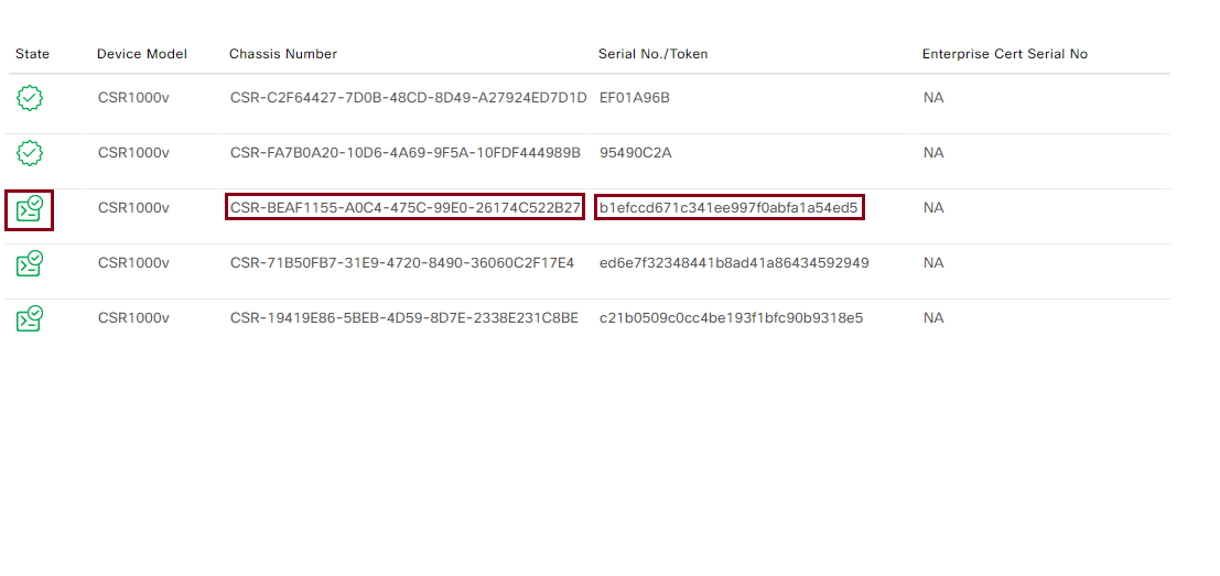
- Step1 Login vManage from https://198.18.133.200:8443. Navigate to the panel on the left and click Configuration - Devices
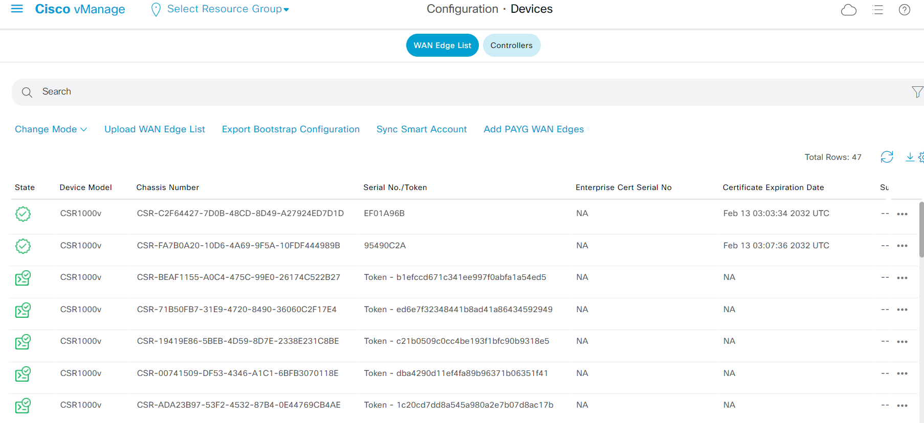
The Chassis Number and Token will be used on next step
-
Step2 Login to br3-ce1 from SSH
-
Step3 In the terminal, enter
request platform software sdwan vedge_cloud activate chassis-number ### token ###where the chassis-number and token are from Step1
request platform software sdwan vedge_cloud activate chassis-number CSR-BEAF1155-A0C4-475C-99E0-26174C522B27 token b1efccd671c341ee997f0abfa1a54ed5
- Step4 Verify the control plane using command
show sdwan control connections
  br3-ce1#show sdwan control connections
                                                                                       PEER                                          PEER                                          CONTROLLER
PEER    PEER PEER            SITE       DOMAIN PEER                                    PRIV  PEER                                    PUB                                           GROUP
TYPE    PROT SYSTEM IP       ID         ID     PRIVATE IP                              PORT  PUBLIC IP                               PORT  ORGANIZATION            LOCAL COLOR     PROXY STATE UPTIME      ID
----------------------------------------------------------------------------------------------------------------------------------------------------------------------------------------
vsmart  dtls 1.1.1.3         1          1      19.1.1.4                                12346 19.1.1.4                                12346 Viptela-POC-Tool - 19827mpls            No    up     0:00:03:22  0
vbond   dtls 0.0.0.0         0          0      19.1.1.2                                12346 19.1.1.2                                12346 Viptela-POC-Tool - 19827mpls            -     up     0:00:03:22  0
vmanage dtls 1.1.1.1         1          0      19.1.1.3                                12446 19.1.1.3                                12446 Viptela-POC-Tool - 19827mpls            No    up     0:00:03:22  0


br3-ce1#
- Step5 Repeat the above steps to onboard br3-ce2
be3-ce2#$ware sdwan vedge_cloud activate chassis-number CSR-71B50FB7-31E9-4720-8490-36060C2F17E4 token ed6e7f32348441b8ad41a86434592949
be3-ce2#
be3-ce2#
be3-ce2#show sdwan control connections
                                                                                       PEER                                          PEER                                          CONTROLLER
PEER    PEER PEER            SITE       DOMAIN PEER                                    PRIV  PEER                                    PUB                                           GROUP
TYPE    PROT SYSTEM IP       ID         ID     PRIVATE IP                              PORT  PUBLIC IP                               PORT  ORGANIZATION            LOCAL COLOR     PROXY STATE UPTIME      ID
----------------------------------------------------------------------------------------------------------------------------------------------------------------------------------------
vbond   dtls 0.0.0.0         0          0      19.1.1.2                                12346 19.1.1.2                                12346 Viptela-POC-Tool - 19827biz-internet    -     up     0:00:00:24  0
vmanage dtls 1.1.1.1         1          0      19.1.1.3                                12446 19.1.1.3                                12446 Viptela-POC-Tool - 19827biz-internet    No    up     0:00:00:24  0
- Step6 Verify the new site from vManage dashboard
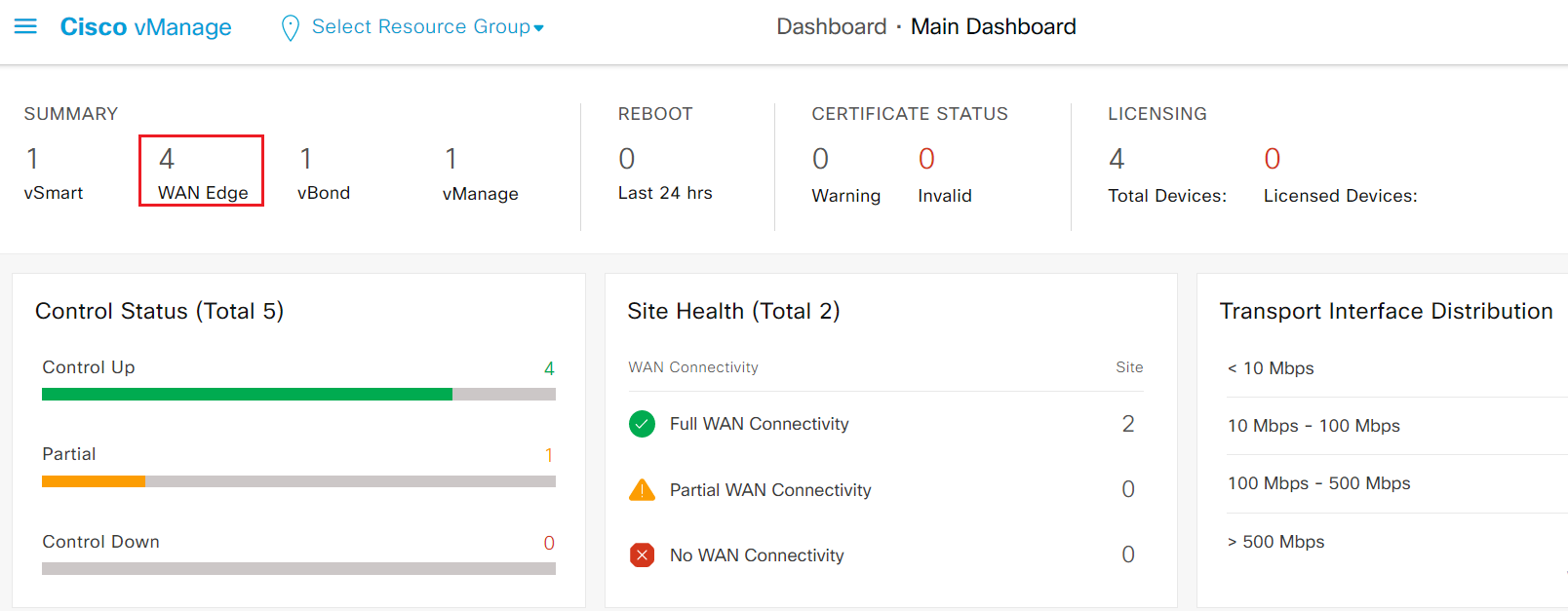
Now you have successfully onboarded new site into the SDWAN fabric.
3.1.7. Develop device template for Site3 CE1 and CE2
In this task, attendee will create one device template that fits for both br3-ce1 and br3-ce2. There are connections between br3-ce1 and br3-ce2 for tloc-ext, which will be task for Day2's lab. Attendee doesn't need to add the tloc-ext interface on the template now.
- Step1 Login to br3-ce1 & br3-ce2 from ssh. Verify interface and IP information for br3-ce1 and br3-ce2
br3-ce1#show ip int b
Interface              IP-Address      OK? Method Status                Protocol
GigabitEthernet1       10.1.3.2        YES other  up                    up
GigabitEthernet2       unassigned      YES unset  up                    up
GigabitEthernet3       unassigned      YES unset  up                    up
GigabitEthernet4       unassigned      YES unset  down                  down
GigabitEthernet5       10.40.100.2     YES other  up                    up
GigabitEthernet6       10.40.200.2     YES other  up                    up
GigabitEthernet7       192.168.40.2    YES other  up                    up
GigabitEthernet8       192.168.150.12  YES other  up                    up
Sdwan-system-intf      1.1.1.5         YES unset  up                    up
Loopback65528          192.168.1.1     YES other  up                    up
NVI0                   unassigned      YES unset  up                    up
Tunnel1                10.1.3.2        YES TFTP   up                    up
br3-ce1#
-
Step2 Login vManage from https://198.18.133.200:8443. Navigate to the panel on the left and click Configuration - Templates, then click Feature tab on the top to switch to the feature template configuration.
- Add the following feature templates for CSR1000v device model
Note: attendee will use factory default for the other required feature templates for building device template. In production deployment, you should always use custom specific feature template
| Template Type | Purpose of the template | Template Name |
|---|---|---|
| Cisco VPN | VPN 0 FT with single static route | CX_VPN0_Static_Route_v01 |
| Cisco VPN Interface Ethernet | VPN 0 transport Interface with static IP | CX_VPN0_Transport1_v01 |
| Cisco VPN | VPN 1 FT with VRRP LAN Side protocol | CX_VPN1_VRRP_v01 |
| Cisco VPN Interface Ethernet | VPN 1 LAN Interface with static IP and VRRP | CX_VPN1_VRRP_Int_v01 |
| Cisco VPN | VPN 2 FT with VRRP LAN Side protocol | CX_VPN2_VRRP_v01 |
| Cisco VPN Interface Ethernet | VPN 2 LAN Interface with static IP and VRRP | CX_VPN2_VRRP_Int_v01 |
| Cisco VPN | VPN 10 FT with VRRP LAN Side protocol | CX_VPN10_VRRP_v01 |
| Cisco VPN Interface Ethernet | VPN 10 LAN Interface with static IP and VRRP | CX_VPN10_VRRP_Int_v01 |
| Cisco VPN | VPN 512 with single static route | CX_VPN512_V01 |
| Cisco VPN Interface Ethernet | VPN 512 LAN Interface with static IP | CX_VPN512_Int_V01 |
- Reference the tables below for each feature template and it's variable. Use default for fields that are not specifically mentioned.
1. CX_VPN0_Static_Route_v01
| Template Name | CX_VPN0_Static_Route_v01 |
|---|---|
| Description | CX_VPN0_Static_Route_v01 |
| VPN | 0 |
| Primary DNS Address (IPv4) | 8.8.8.8 |
| New Host Mapping | |
| Hostname | vbond-test-drive |
| List of IP Address | 19.1.1.2 |
| IPV4 ROUTE | |
| Prefix | 0.0.0.0/0 |
| Gateway | Next Hop |
| Next Hop Device Specific variable | vpn0_default_next_hop1 |
2. CX_VPN0_Transport1_v01
| Template | CX_VPN0_Transport1_v01 |
|---|---|
| Shutdown Device Specific variable | vpn0_transport1_shut |
| Interface Name Device Specific variable | vpn0_transport1_intf |
| Static IP | |
| IPv4 Address Device Specific variable | vpn0_transport1_IP_addr |
| TUNNEL | |
| Tunnel Interface | On |
| Color Device Specific variable | vpn0_transport1_color |
| Restrict Device Specific variable | vpn0_transport1_restict |
3. CX_VPN1_VRRP_v01
| Template Name | CX_VPN1_VRRP_v01 |
|---|---|
| Description | CX_VPN1_VRRP_v01 |
| VPN | 1 |
| Advertise OMP | Connected |
4. CX_VPN1_VRRP_Int_v01
| Template | CX_VPN1_VRRP_Int_v01 |
|---|---|
| Shutdown Device Specific variable | vpn1_intf_shut |
| Interface Name Device Specific variable | vpn1_intf |
| Static IP | |
| IPv4 Address Device Specific variable | vpn1_IP_addr |
| VRRP | |
| Group ID | 1 |
| Priority Device Specific variable | vpn1_vrrp_priority |
| IP Address Device Specific variable | vpn1_vrrp_IP |
5. CX_VPN2_VRRP_v01
| Template Name | CX_VPN2_VRRP_v01 |
|---|---|
| Description | CX_VPN2_VRRP_v01 |
| VPN | 2 |
| Advertise OMP | Connected |
6. CX_VPN2_VRRP_Int_v01
| Template | CX_VPN2_VRRP_Int_v01 |
|---|---|
| Shutdown Device Specific variable | vpn2_intf_shut |
| Interface Name Device Specific variable | vpn2_intf |
| Static IP | |
| IPv4 Address Device Specific variable | vpn2_IP_addr |
| VRRP | |
| Group ID | 1 |
| Priority Device Specific variable | vpn2_vrrp_priority |
| IP Address Device Specific variable | vpn2_vrrp_IP |
7. CX_VPN10_VRRP_v01
| Template Name | CX_VPN10_VRRP_v01 |
|---|---|
| Description | CX_VPN10_VRRP_v01 |
| VPN | 10 |
| Advertise OMP | Connected |
8. CX_VPN10_VRRP_Int_v01
| Template | CX_VPN10_VRRP_Int_v01 |
|---|---|
| Shutdown Device Specific variable | vpn10_intf_shut |
| Interface Name Device Specific variable | vpn10_intf |
| Static IP | |
| IPv4 Address Device Specific variable | vpn10_IP_addr |
| VRRP | |
| Group ID | 1 |
| Priority Device Specific variable | vpn10_vrrp_priority |
| IP Address Device Specific variable | vpn10_vrrp_IP |
9. CX_VPN512_V01
| Template Name | CX_VPN512_V01 |
|---|---|
| Description | CX_VPN512_V01 |
| VPN | 512 |
| IPV4 ROUTE | |
| Prefix | 0.0.0.0/0 |
| Gateway | Next Hop |
| Next Hop Global | 192.168.150.1 |
10. CX_VPN512_Int_V01
| Template | CX_VPN512_Int_V01 |
|---|---|
| Shutdown Device Specific variable | vpn512_intf_shut |
| Interface Name Device Specific variable | vpn512_intf |
| Static IP | |
| IPv4 Address Device Specific variable | vpn512_IP_addr |
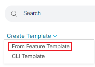
- Step3 Click on Device tab on the top of Templates Configuration to switch to Device template configuration.
- Step4 Click Create Template drop down menu and select From Feature Template
- Step5 Create the device template as show in tabel below
| Device Model | CSR1000v |
|---|---|
| Device Role | SDWAN Edge |
| Template Name | CX_CSR1Kv_SIte3_v01 |
| Description | CX_CSR1Kv_SIte3_v01 |
| Basic Information | |
| Cisco System | Default_BootStrap_Cisco_System_Template |
| Cisco Logging | Default_Logging_Cisco_V01 |
| Cisco AAA | Factory_Default_AAA_CISCO_Template |
| Cisco OMP | Default_AWS_TGW_CSR_OMP_IPv46_V01 |
| Cisco BFD | Default_BFD_Cisco_V01 |
| Cisco Security | Default_Security_Cisco_V01 |
| Transport & Management VPN | |
| Cisco VPN 0 | CX_VPN0_Static_Route_v01 |
| Cisco VPN Interface Ethernet | CX_VPN0_Transport1_v01 |
| Cisco VPN 512 | CX_VPN512_V01 |
| Service VPN | |
| Add VPN | CX_VPN1_VRRP_v01 |
| Cisco VPN Interface Ethernet | CX_VPN1_VRRP_Int_v01 |
| Add VPN | CX_VPN2_VRRP_v01 |
| Cisco VPN Interface Ethernet | CX_VPN2_VRRP_Int_v01 |
| Add VPN | CX_VPN10_VRRP_v01 |
| Cisco VPN Interface Ethernet | CX_VPN10_VRRP_Int_v01 |
Click Create to create the device template
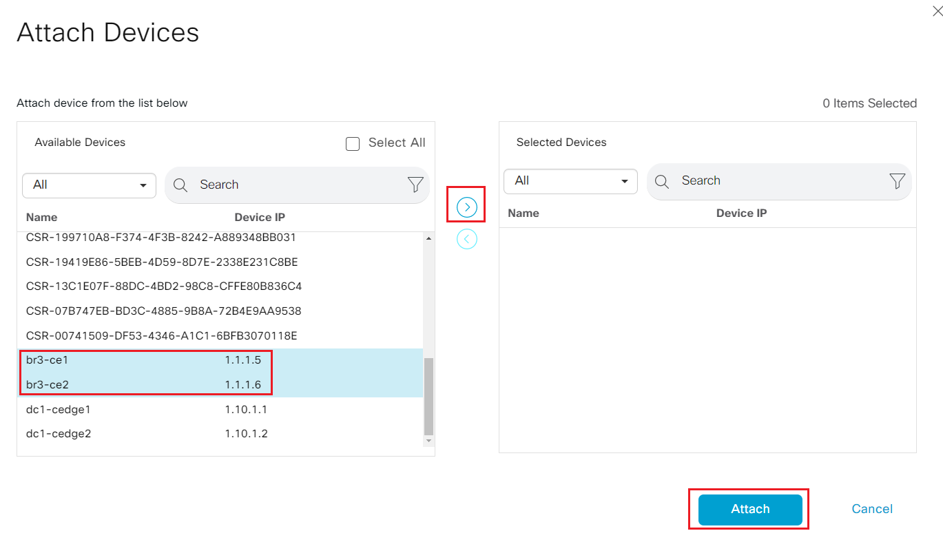
- Step6 Back to the device template configuration portal; locate the newly created CX_CSR1Kv_SIte3_v01; click on the ... and select Attach Devices
- Step7 highlight br3-ce1 and br3-ce2 on the left, and lick the > to move it selected Devices, then click Attach
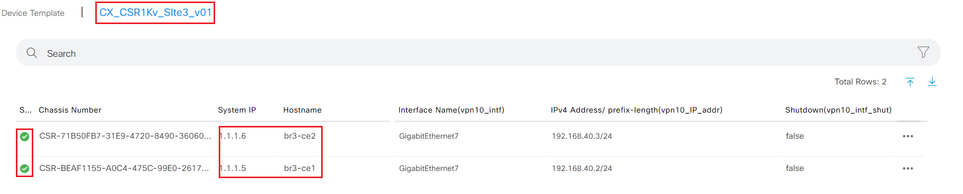
- Step8 Fill in the value as show in the table for each device
| System IP | 1.1.1.5 |
|---|---|
| Hostname | br3-ce1 |
| Interface Name(vpn10_intf) | GigabitEthernet7 |
| IPv4 Address/ prefix-length(vpn10_IP_addr) | 192.168.40.2/24 |
| Shutdown(vpn10_intf_shut) | uncheck |
| Priority(vpn10_vrrp_priority) | 110 |
| IP Address(vpn10_vrrp_IP) | 192.168.40.1 |
| Interface Name(vpn2_intf) | GigabitEthernet6 |
| IPv4 Address/ prefix-length(vpn2_IP_addr) | 10.40.200.2/24 |
| Shutdown(vpn2_intf_shut) | uncheck |
| Priority(vpn2_vrrp_priority) | 110 |
| IP Address(vpn2_vrrp_IP) | 10.40.200.1 |
| Interface Name(vpn1_intf) | GigabitEthernet5 |
| IPv4 Address/ prefix-length(vpn1_IP_addr) | 10.40.100.2/24 |
| Shutdown(vpn1_intf_shut) | uncheck |
| Priority(vpn1_vrrp_priority) | 110 |
| IP Address(vpn1_vrrp_IP) | 10.40.100.1 |
| Interface Name(vpn512_intf) | GigabitEthernet8 |
| IPv4 Address/ prefix-length(vpn512_IP_addr) | 192.168.150.12/24 |
| Shutdown(vpn512_intf_shut) | uncheck |
| Address(vpn0_default_next_hop1) | 10.1.3.1 |
| Interface Name(vpn0_transport1_intf) | GigabitEthernet1 |
| IPv4 Address/ prefix-length(vpn0_transport1_IP_addr) | 10.1.3.2/24 |
| Color(vpn0_transport1_color) | mpls |
| Restrict(vpn0_transport1_restict) | check |
| Shutdown(vpn0_transport1_shut) | uncheck |
| Hostname | br3-ce1 |
| System IP | 1.1.1.5 |
| Site ID | 300 |
| System IP | 1.1.1.6 |
|---|---|
| Hostname | br3-ce2 |
| Interface Name(vpn10_intf) | GigabitEthernet7 |
| IPv4 Address/ prefix-length(vpn10_IP_addr) | 192.168.40.3/24 |
| Shutdown(vpn10_intf_shut) | uncheck |
| Priority(vpn10_vrrp_priority) | 100 |
| IP Address(vpn10_vrrp_IP) | 192.168.40.1 |
| Interface Name(vpn2_intf) | GigabitEthernet6 |
| IPv4 Address/ prefix-length(vpn2_IP_addr) | 10.40.200.3/24 |
| Shutdown(vpn2_intf_shut) | uncheck |
| Priority(vpn2_vrrp_priority) | 100 |
| IP Address(vpn2_vrrp_IP) | 10.40.200.1 |
| Interface Name(vpn1_intf) | GigabitEthernet5 |
| IPv4 Address/ prefix-length(vpn1_IP_addr) | 10.40.100.3/24 |
| Shutdown(vpn1_intf_shut) | uncheck |
| Priority(vpn1_vrrp_priority) | 100 |
| IP Address(vpn1_vrrp_IP) | 10.40.100.1 |
| Interface Name(vpn512_intf) | GigabitEthernet8 |
| IPv4 Address/ prefix-length(vpn512_IP_addr) | 192.168.150.13/24 |
| Shutdown(vpn512_intf_shut) | uncheck |
| Address(vpn0_default_next_hop1) | 19.1.4.1 |
| Interface Name(vpn0_transport1_intf) | GigabitEthernet2 |
| IPv4 Address/ prefix-length(vpn0_transport1_IP_addr) | 19.1.4.6/24 |
| Color(vpn0_transport1_color) | biz-internet |
| Restrict(vpn0_transport1_restict) | uncheck |
| Shutdown(vpn0_transport1_shut) | uncheck |
| Hostname | br3-ce2 |
| System IP | 1.1.1.6 |
| Site ID | 300 |
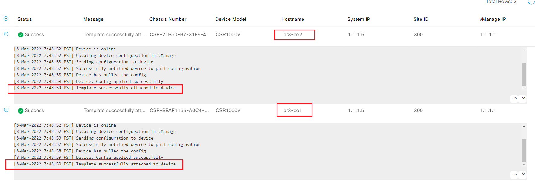
- Step9 After system verify the entered variable's format, Click Next - Configure Devices
- Step10 Wait for vManage successfully attached to device message
- Step10 Login to br3-ce1 and br3-ce2 from ssh; verify sdwan tunnels and vrrp status
br3-ce1#show sdwan control connections
                                                                                       PEER                                          PEER                                          CONTROLLER
PEER    PEER PEER            SITE       DOMAIN PEER                                    PRIV  PEER                                    PUB                                           GROUP
TYPE    PROT SYSTEM IP       ID         ID     PRIVATE IP                              PORT  PUBLIC IP                               PORT  ORGANIZATION            LOCAL COLOR     PROXY STATE UPTIME      ID
----------------------------------------------------------------------------------------------------------------------------------------------------------------------------------------
vsmart  dtls 1.1.1.3         1          1      19.1.1.4                                12346 19.1.1.4                                12346 Viptela-POC-Tool - 19827mpls            No    up     1:18:27:56  0
vbond   dtls 0.0.0.0         0          0      19.1.1.2                                12346 19.1.1.2                                12346 Viptela-POC-Tool - 19827mpls            -     up     1:18:27:57  0
vmanage dtls 1.1.1.1         1          0      19.1.1.3                                12446 19.1.1.3                                12446 Viptela-POC-Tool - 19827mpls            No    up     1:18:27:56  0


br3-ce1#show sdwan bfd ses
br3-ce1#show sdwan bfd sessions
                                      SOURCE TLOC      REMOTE TLOC                                      DST PUBLIC                      DST PUBLIC         DETECT      TX
SYSTEM IP        SITE ID  STATE       COLOR            COLOR            SOURCE IP                       IP                              PORT        ENCAP  MULTIPLIER  INTERVAL(msec  UPTIME          TRANSITIONS
------------------------------------------------------------------------------------------------------------------------------------------------------------------------------------------------------------------
1.10.1.1         10       up          mpls             mpls             10.1.3.2                        10.1.0.2                        12346       ipsec  7           1000           10 1:18:28:00   1
1.10.1.2         10       up          mpls             mpls             10.1.3.2                        10.1.1.2                        12346       ipsec  7           1000           10 1:18:28:00   1

br3-ce1#
br3-ce1#show vrrp brief
  Interface          Grp  A-F Pri  Time Own Pre State   Master addr/Group addr
  Gi5                  1 IPv4 110     0  N   Y  MASTER  10.40.100.2(local) 10.40.100.1
  Gi6                  1 IPv4 110     0  N   Y  MASTER  10.40.200.2(local) 10.40.200.1
  Gi7                  1 IPv4 110     0  N   Y  MASTER  192.168.40.2(local) 192.168.40.1
br3-ce1#
br3-ce2#show sdwan control connections
                                                                                       PEER                                          PEER                                          CONTROLLER
PEER    PEER PEER            SITE       DOMAIN PEER                                    PRIV  PEER                                    PUB                                           GROUP
TYPE    PROT SYSTEM IP       ID         ID     PRIVATE IP                              PORT  PUBLIC IP                               PORT  ORGANIZATION            LOCAL COLOR     PROXY STATE UPTIME      ID
----------------------------------------------------------------------------------------------------------------------------------------------------------------------------------------
vsmart  dtls 1.1.1.3         1          1      19.1.1.4                                12346 19.1.1.4                                12346 Viptela-POC-Tool - 19827biz-internet    No    up     1:18:28:43  0
vbond   dtls 0.0.0.0         0          0      19.1.1.2                                12346 19.1.1.2                                12346 Viptela-POC-Tool - 19827biz-internet    -     up     1:18:28:44  0
vmanage dtls 1.1.1.1         1          0      19.1.1.3                                12446 19.1.1.3                                12446 Viptela-POC-Tool - 19827biz-internet    No    up     1:18:28:43  0


br3-ce2#show sdwan bfd ses
br3-ce2#show sdwan bfd sessions
                                      SOURCE TLOC      REMOTE TLOC                                      DST PUBLIC                      DST PUBLIC         DETECT      TX
SYSTEM IP        SITE ID  STATE       COLOR            COLOR            SOURCE IP                       IP                              PORT        ENCAP  MULTIPLIER  INTERVAL(msec  UPTIME          TRANSITIONS
------------------------------------------------------------------------------------------------------------------------------------------------------------------------------------------------------------------
1.10.1.2         10       up          biz-internet     biz-internet     19.1.4.6                        19.1.2.2                        12346       ipsec  7           1000           10 1:18:28:45   1
1.10.1.1         10       up          biz-internet     biz-internet     19.1.4.6                        19.1.23.3                       12346       ipsec  7           1000           10 1:18:28:45   1

br3-ce2#show vrrp brief
  Interface          Grp  A-F Pri  Time Own Pre State   Master addr/Group addr
  Gi5                  1 IPv4 100   360  N   Y  BACKUP  10.40.100.2 10.40.100.1
  Gi6                  1 IPv4 100   360  N   Y  BACKUP  10.40.200.2 10.40.200.1
  Gi7                  1 IPv4 100   360  N   Y  BACKUP  192.168.40.2 192.168.40.1
3.1.8. Verify reachability from Site3 to other sites
In this task, attendee will verify connectivity from site3 to other SDWAN site and non-SDWAN site
- Step1 login to br3-vm1 from SSH or VNC.
- Run
ping 10.30.100.100to verify connectivity to VM in legacy site - Run
ping 10.10.100.100to verify connectivity to VM in DC - Attendee can also verify first hop redundancy by shutdown the LAN interface on br-ce1 and verify the connectivity from br3-vm1
viptela@ubuntu:~$ ping 10.30.100.100
PING 10.30.100.100 (10.30.100.100) 56(84) bytes of data.
64 bytes from 10.30.100.100: icmp_seq=2 ttl=59 time=7.13 ms
64 bytes from 10.30.100.100: icmp_seq=3 ttl=59 time=11.0 ms
64 bytes from 10.30.100.100: icmp_seq=4 ttl=59 time=9.50 ms
64 bytes from 10.30.100.100: icmp_seq=5 ttl=59 time=8.10 ms
64 bytes from 10.30.100.100: icmp_seq=6 ttl=59 time=14.4 ms
64 bytes from 10.30.100.100: icmp_seq=7 ttl=59 time=9.65 ms
64 bytes from 10.30.100.100: icmp_seq=8 ttl=59 time=8.10 ms
64 bytes from 10.30.100.100: icmp_seq=9 ttl=59 time=8.98 ms
^[[A64 bytes from 10.30.100.100: icmp_seq=10 ttl=59 time=9.90 ms
^[[A64 bytes from 10.30.100.100: icmp_seq=11 ttl=59 time=8.78 ms
64 bytes from 10.30.100.100: icmp_seq=12 ttl=59 time=7.33 ms
^C
--- 10.30.100.100 ping statistics ---
12 packets transmitted, 11 received, 8% packet loss, time 11013ms
rtt min/avg/max/mdev = 7.139/9.365/14.417/1.945 ms
viptela@ubuntu:~$ ping 10.10.100.100
PING 10.10.100.100 (10.10.100.100) 56(84) bytes of data.
64 bytes from 10.10.100.100: icmp_seq=1 ttl=61 time=10.9 ms
64 bytes from 10.10.100.100: icmp_seq=2 ttl=61 time=11.6 ms
64 bytes from 10.10.100.100: icmp_seq=3 ttl=61 time=6.23 ms
64 bytes from 10.10.100.100: icmp_seq=4 ttl=61 time=8.54 ms
64 bytes from 10.10.100.100: icmp_seq=5 ttl=61 time=13.6 ms

--- 10.10.100.100 ping statistics ---
5 packets transmitted, 5 received, 0% packet loss, time 4005ms
rtt min/avg/max/mdev = 6.234/10.191/13.629/2.561 ms
viptela@ubuntu:~$
CONFIGURATION! This concludes all tasks for day1's lab. You have completed the following tasks
- Configured OSPF as LAN side routing protocol using vManage feature template
- Configured DC as transit site between SDWAN and non SDWAN site
- Onboarded b3-ce1 and br3-ce2 to SDWAN fabric
- Created device template for site3 wan edges using customized feature templates
- Added site3 into the SDWAN fabric and validated connectivity to other sdwan site and non sdwan site