3.2. Day 2 tasks
In Day'2 lab, attendee will first learn how to manually onboard the virtual cedge with minimal configuration. After that, attendee will migrate a site from non-sdwan to sdwan without introducing big service disruption. The same strategy can be used in real world site migration.
The tloc-ext is a common feature used for remote site deployment. Attendee will learn how to create tloc-ext on an existing SDWAN site to increase the site transport redundancy.
Centralized policy is the most powerful feature offered by Cisco SDWAN solution. Attendee will learn how to configure the most common hub & spoke topology using Centralized control policy.
3.2.1. Onboard BR1-CE1
In this task, attendee will onboard br1-ce1 to the fabric. Unlike the task from Day1 which br3-ce1/br3-ce2 are pre-configured with minimal configuration, in this task, attendee will configure the minimal configured required to onboard br1-ce1.
-
Step1 Login to br1-ce1 from ssh (mgmt IP is preconfigured for ssh). Enter
show sdwan runningto verify no existing configuration besides the management IP. -
Step2 Configure the WAN interfaces and commit the change.
Router#config-transaction

admin connected from 127.0.0.1 using console on Router
Router(config)# interface GigabitEthernet 1
Router(config-if)# ip address 10.1.2.2 255.255.255.0
Router(config-if)# no shu
Router(config-if)# exit
Router(config)# interface GigabitEthernet 2
Router(config-if)# ip address dhcp
Router(config-if)# no shut
Router(config-if)# exi
Router(config)# ip route 0.0.0.0 0.0.0.0 10.1.2.1
Router(config)# commit
Commit complete.
- Step3 Verify reachability to vBond, vManage, vSmart IP
Router#ping 19.1.1.3
Type escape sequence to abort.
Sending 5, 100-byte ICMP Echos to 19.1.1.3, timeout is 2 seconds:
!!!!!
Success rate is 100 percent (5/5), round-trip min/avg/max = 2/4/9 ms
Router#ping 19.1.1.4
Type escape sequence to abort.
Sending 5, 100-byte ICMP Echos to 19.1.1.4, timeout is 2 seconds:
!!!!!
Success rate is 100 percent (5/5), round-trip min/avg/max = 3/3/4 ms
Router#ping 19.1.1.2
Type escape sequence to abort.
Sending 5, 100-byte ICMP Echos to 19.1.1.2, timeout is 2 seconds:
!!!!!
Success rate is 100 percent (5/5), round-trip min/avg/max = 10/26/33 ms
Router#
- Step4 Configure the required minimal SDWAN information such as, system-ip, site-id, organization name, vbond information and tunnel interfaces.
system
 system-ip             1.1.1.4
 overlay-id            1
 site-id               100
 port-offset           0
 control-session-pps   300
 admin-tech-on-failure
 sp-organization-name  "Viptela-POC-Tool - 19827"
 organization-name     "Viptela-POC-Tool - 19827"
 port-hop
 track-transport
 track-default-gateway
 console-baud-rate     9600
 no on-demand enable
 on-demand idle-timeout 10
 vbond vbond-test-drive port 12346

ip host vbond-test-drive 19.1.1.2

interface Tunnel1
 no shutdown
 ip unnumbered GigabitEthernet1
 no ip redirects
 ipv6 unnumbered GigabitEthernet1
 no ipv6 redirects
 tunnel source GigabitEthernet1
 tunnel mode sdwan

interface Tunnel2
 no shutdown
 ip unnumbered GigabitEthernet2
 no ip redirects
 ipv6 unnumbered GigabitEthernet2
 no ipv6 redirects
 tunnel source GigabitEthernet2
 tunnel mode sdwan

sdwan
 interface GigabitEthernet1
  tunnel-interface
   encapsulation ipsec weight 1
   no border
   color mpls restrict

 interface GigabitEthernet2
  tunnel-interface
   encapsulation ipsec weight 1
   no border
   color biz-internet
- Step5 Run
show clockon br1-ce1 to verify clock is in-sync - Taks6 Login vManage from https://198.18.133.200:8443. Navigate to the panel on the left and click Configuration - Devices. Locate one unused CSR1000v, the Chassis Number and Token will be used on next step.
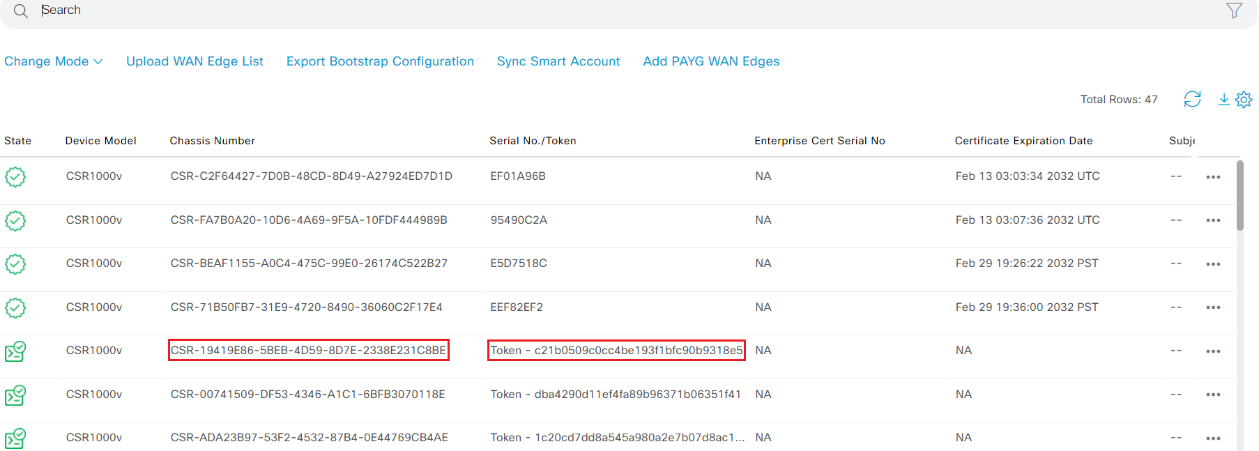
- Taks7 In the terminal, enter
request platform software sdwan vedge_cloud activate chassis-number ### token ###where the chassis-number and token are from Step6
Router#$ware sdwan vedge_cloud activate chassis-number CSR-19419E86-5BEB-4D59-8D7E-2338E231C8BE to c21b0509c0cc4be193f1bfc90b9318e5
Router#
- Step8 Verify the control plane using command
show sdwan control connections
Router#show sdwan control connections
                                                                                       PEER                                          PEER                                          CONTROLLER
PEER    PEER PEER            SITE       DOMAIN PEER                                    PRIV  PEER                                    PUB                                           GROUP
TYPE    PROT SYSTEM IP       ID         ID     PRIVATE IP                              PORT  PUBLIC IP                               PORT  ORGANIZATION            LOCAL COLOR     PROXY STATE UPTIME      ID
----------------------------------------------------------------------------------------------------------------------------------------------------------------------------------------
vsmart  dtls 1.1.1.3         1          1      19.1.1.4                                12346 19.1.1.4                                12346 Viptela-POC-Tool - 19827mpls            No    up     0:00:00:48  0
vbond   dtls 0.0.0.0         0          0      19.1.1.2                                12346 19.1.1.2                                12346 Viptela-POC-Tool - 19827mpls            -     up     0:00:00:48  0
vbond   dtls 0.0.0.0         0          0      19.1.1.2                                12346 19.1.1.2                                12346                         biz-internet    -     connect            0
vmanage dtls 1.1.1.1         1          0      19.1.1.3                                12346 19.1.1.3                                12346 Viptela-POC-Tool - 19827mpls            No    up     0:00:00:48  0
- Step9 br1-ce1 has two transport, one for MPLS and one for Internet. Add one Cisco VPN Interface Ethernet feature template for 2nd transport interface with following setting. CX_VPN0_Transport2_DCHP_v01
| Template | CX_VPN0_Transport2_DHCP_v01 |
|---|---|
| Shutdown Device Specific variable | vpn0_transport2_shut |
| Interface Name Device Specific variable | vpn0_transport2_intf |
| Dynamic IP | |
| TUNNEL | |
| Tunnel Interface | On |
| Color Device Specific variable | vpn0_transport2_color |
| Restrict Device Specific variable | vpn0_transport2_restict |
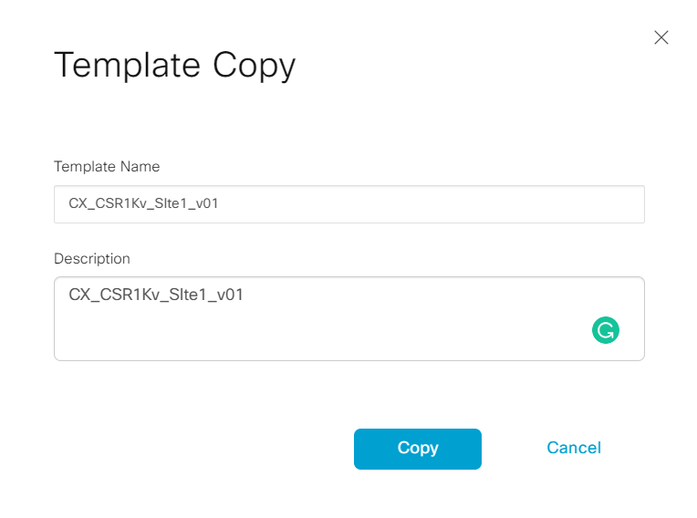
- Step10 Locate device template CX_CSR1Kv_SIte3_v01; select the ... and click Copy

- Step11 Name the template copy CX_CSR1Kv_SIte1_v01
-
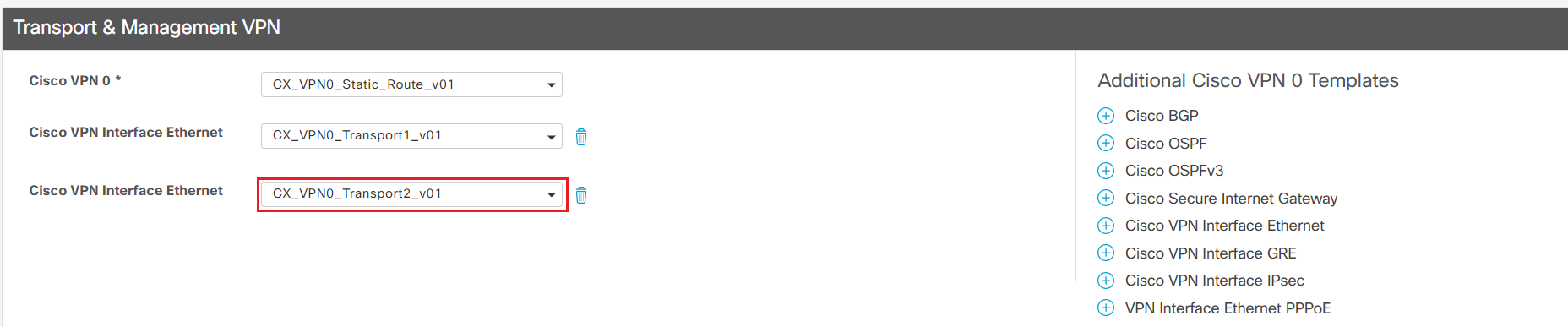
Step12 Locate the newly created template CX_CSR1Kv_SIte1_v01; select the ... and click Edit
-
Step13 Under Transport & Management VPN section, add CX_VPN0_Transport2_DHCP_v01 as 2nd VPN interface.
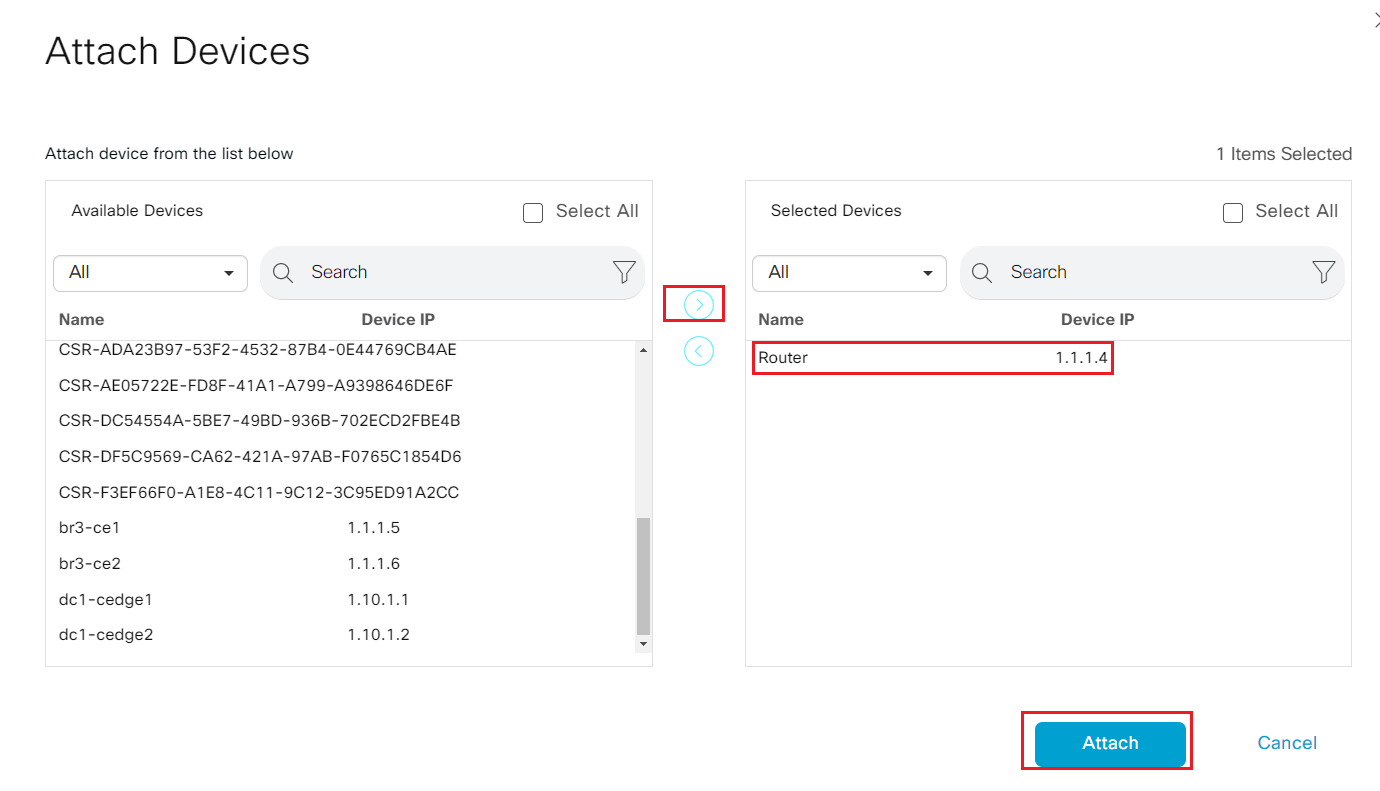
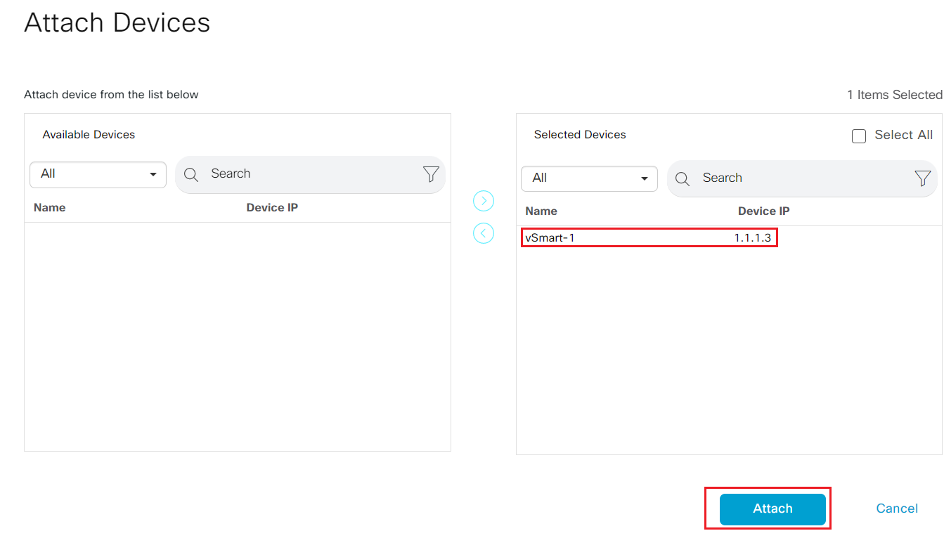
- Step14 After update it, locate template CX_CSR1Kv_SIte1_v01; select the ... and click Attach Devices.
- Step15 Select Router 1.1.1.4 from left available devices panel and move it to the right Selected devices panel.
- Step16 Fill in the value as show in the table
| System IP | 1.1.1.4 |
|---|---|
| Hostname | br1-ce1 |
| Interface Name(vpn10_intf) | GigabitEthernet6 |
| IPv4 Address/ prefix-length(vpn10_IP_addr) | 192.168.10.3/24 |
| Shutdown(vpn10_intf_shut) | uncheck |
| Priority(vpn10_vrrp_priority) | 110 |
| IP Address(vpn10_vrrp_IP) | 192.168.10.1 |
| Interface Name(vpn2_intf) | GigabitEthernet5 |
| IPv4 Address/ prefix-length(vpn2_IP_addr) | 10.200.200.3/24 |
| Shutdown(vpn2_intf_shut) | uncheck |
| Priority(vpn2_vrrp_priority) | 90 |
| IP Address(vpn2_vrrp_IP) | 10.200.200.1 |
| Interface Name(vpn1_intf) | GigabitEthernet4 |
| IPv4 Address/ prefix-length(vpn1_IP_addr) | 10.200.100.3/24 |
| Shutdown(vpn1_intf_shut) | uncheck |
| Priority(vpn1_vrrp_priority) | 90 |
| IP Address(vpn1_vrrp_IP) | 10.200.100.1 |
| Interface Name(vpn512_intf) | GigabitEthernet8 |
| IPv4 Address/ prefix-length(vpn512_IP_addr) | 192.168.150.9/24 |
| Shutdown(vpn512_intf_shut) | uncheck |
| Address(vpn0_default_next_hop1) | 10.1.2.1 |
| Interface Name(vpn0_transport2_intf) | GigabitEthernet2 |
| Color(vpn0_transport2_color) | biz-internet |
| Restrict(vpn0_transport2_restict) | uncheck |
| Shutdown(vpn0_transport1_shut) | uncheck |
| Interface Name(vpn0_transport1_intf) | GigabitEthernet1 |
| IPv4 Address/ prefix-length(vpn0_transport1_IP_addr) | 10.1.2.2/24 |
| Color(vpn0_transport1_color) | mpls |
| Restrict(vpn0_transport1_restict) | check |
| Shutdown(vpn0_transport1_shut) | uncheck |
| Hostname | br1-ce1 |
| System IP | 1.1.1.4 |
| Site ID | 100 |
-
Step17 After system verify the entered variable's format, Click Next - Configure Devices
-
Step18 Login to br1-ce1 from ssh; verify sdwan tunnels and vrrp status
br1-ce1#show sdwan control connections
                                                                                       PEER                                          PEER                                          CONTROLLER
PEER    PEER PEER            SITE       DOMAIN PEER                                    PRIV  PEER                                    PUB                                           GROUP
TYPE    PROT SYSTEM IP       ID         ID     PRIVATE IP                              PORT  PUBLIC IP                               PORT  ORGANIZATION            LOCAL COLOR     PROXY STATE UPTIME      ID
----------------------------------------------------------------------------------------------------------------------------------------------------------------------------------------
vsmart  dtls 1.1.1.3         1          1      19.1.1.4                                12346 19.1.1.4                                12346 Viptela-POC-Tool - 19827mpls            No    up     0:00:07:22  0
vsmart  dtls 1.1.1.3         1          1      19.1.1.4                                12346 19.1.1.4                                12346 Viptela-POC-Tool - 19827biz-internet    No    up     0:00:07:16  0
vbond   dtls 0.0.0.0         0          0      19.1.1.2                                12346 19.1.1.2                                12346 Viptela-POC-Tool - 19827mpls            -     up     0:00:07:23  0
vbond   dtls 0.0.0.0         0          0      19.1.1.2                                12346 19.1.1.2                                12346 Viptela-POC-Tool - 19827biz-internet    -     up     0:00:07:17  0
vmanage dtls 1.1.1.1         1          0      19.1.1.3                                12346 19.1.1.3                                12346 Viptela-POC-Tool - 19827mpls            No    up     0:00:07:23  0


br1-ce1#show sdwan bfd session
                                      SOURCE TLOC      REMOTE TLOC                                      DST PUBLIC                      DST PUBLIC         DETECT      TX
SYSTEM IP        SITE ID  STATE       COLOR            COLOR            SOURCE IP                       IP                              PORT        ENCAP  MULTIPLIER  INTERVAL(msec  UPTIME          TRANSITIONS
------------------------------------------------------------------------------------------------------------------------------------------------------------------------------------------------------------------
1.10.1.1         10       up          mpls             mpls             10.1.2.2                        10.1.0.2                        12346       ipsec  7           1000           10 0:00:07:26   1
1.10.1.2         10       up          mpls             mpls             10.1.2.2                        10.1.1.2                        12346       ipsec  7           1000           10 0:00:07:25   1
1.1.1.5          300      up          mpls             mpls             10.1.2.2                        10.1.3.2                        12366       ipsec  7           1000           10 0:00:07:25   1
1.10.1.2         10       up          biz-internet     biz-internet     19.1.3.6                        19.1.2.2                        12346       ipsec  7           1000           10 0:00:07:21   0
1.1.1.6          300      up          biz-internet     biz-internet     19.1.3.6                        19.1.4.6                        12346       ipsec  7           1000           10 0:00:07:21   0
1.10.1.1         10       up          biz-internet     biz-internet     19.1.3.6                        19.1.23.3                       12346       ipsec  7           1000           10 0:00:07:20   0

br1-ce1#show vrrp brief
  Interface          Grp  A-F Pri  Time Own Pre State   Master addr/Group addr
  Gi4                  1 IPv4  90  3648  N   Y  BACKUP  10.200.100.2 10.200.100.1
  Gi5                  1 IPv4  90  3648  N   Y  BACKUP  10.200.200.2 10.200.200.1
  Gi6                  1 IPv4 110     0  N   Y  MASTER  192.168.10.3(local) 192.168.10.1
3.2.2. Make BR1-CE1 as VRRP primary
In this task, attendee will migrate branch1 from legacy to SDWAN fabric by modifying the VRRP priority on br1-ce1. Note Optionally you can verify the packet loss by send continually ping from br1-vm1
Last login: Mon Feb 14 21:48:53 2022
viptela@ubuntu:~$ ping 10.40.100.100
PING 10.40.100.100 (10.40.100.100) 56(84) bytes of data.
64 bytes from 10.40.100.100: icmp_seq=2 ttl=62 time=6.79 ms
64 bytes from 10.40.100.100: icmp_seq=3 ttl=62 time=8.57 ms
64 bytes from 10.40.100.100: icmp_seq=4 ttl=62 time=8.94 ms
- Step1 Login vManage from https://198.18.133.200:8443. Navigate to the panel on the left and click Configuration - Templates. Locate device template CX_CSR1Kv_SIte1_v01, click ... and select Change Device Values
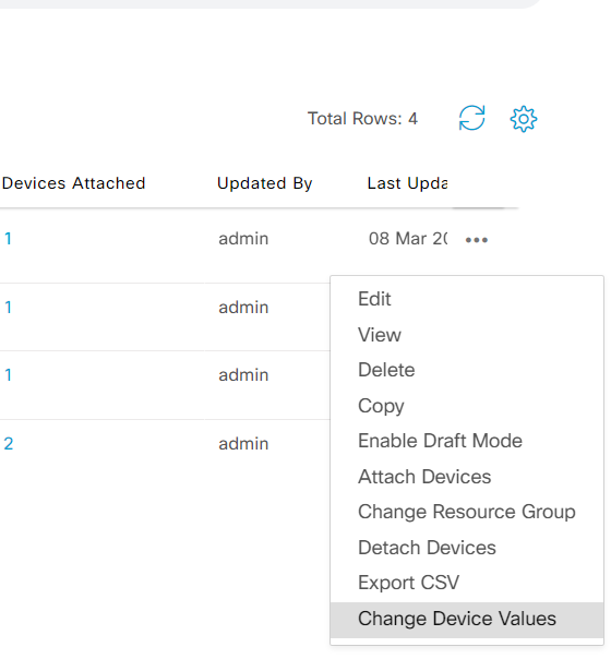
-
Step2 Change Priority for vpn1_vrrp_priority,vpn2_vrrp_priority to 110. Update the template to push configuration change.
-
Step3 Login to br1-ce1 to verify the VRRP status
 br1-ce1#show vrrp bri
br1-ce1#show vrrp brief
  Interface          Grp  A-F Pri  Time Own Pre State   Master addr/Group addr
  Gi4                  1 IPv4 110     0  N   Y  MASTER  10.200.100.3(local) 10.200.100.1
  Gi5                  1 IPv4 110     0  N   Y  MASTER  10.200.200.3(local) 10.200.200.1
  Gi6                  1 IPv4 110     0  N   Y  MASTER  192.168.10.3(local) 192.168.10.1
br1-ce1#
3.2.3. Verify reachability from Site1 to other sites
In this task, attendee will remove the old non-SDWAN router from br1 and verify the connectivity from br1-vm1.
-
Login to br1-vm1 from SSH or VNC; run
ping 10.40.100.100to check connectivity to br3-vm1 in the sdwan fabric -
Login to site1 legacy router site1-r1 form SSH. Shutdown interface "GigabitEthernet1", "GigabitEthernet4","GigabitEthernet5" to emulate decommission the router.
 site1-r1#conf t
Enter configuration commands, one per line.  End with CNTL/Z.
site1-r1(config)#interface g1
site1-r1(config-if)#shu
site1-r1(config-if)#int g4
site1-r1(config-if)#shu
site1-r1(config-if)#int g5
site1-r1(config-if)#shu
site1-r1(config-if)#
- Verify the br1-vm1 still have connectivity to other sites.
3.2.4. Build Tloc-ext for Site3
In this task, attendee will add transport redundancy for site3. There are two connections between br3-ce1 and br3-ce2. The tloc extension interface is GigabitEthernet3 on both edge routers. br3-ce1 GigabitEthernet3 connects to br3-ce2 GigabitEthernet1, and br3-ce2 GigabitEthernet3 connects to br3-ce1 GigabitEthernet2.
In real world deployment, MPLS transport over TLOC-Ext typically uses BGP to advertise IP for TLOC Extension, so controllers and other WAN Edges can reach the TLOC. Internet transport over TLOC-Ext uses NAT to translate the IP for TLOC Extension, so controllers and other WAN Edge can reach the TLOC. In the lab, static routes are pre-configured on transport network to provide reachability for transports over TLOC-Ext. BGP and NAT are not required to build TLOC-Ext for this lab, but in production BGP and NAT are typically required for TLOC-Ext.
- Step1 Add following feature templates for TLOC-Ext
| Template Type | Purpose of the template | Template Name |
|---|---|---|
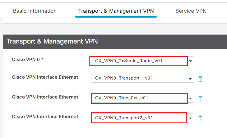
| Cisco VPN | VPN 0 FT with 2 static default route | CX_VPN0_2xStatic_Route_v01 |
| Cisco VPN Interface Ethernet | VPN 0 transport Interface 2 with static IP | CX_VPN0_Transport2_v01 |
| Cisco VPN Interface Ethernet | VPN 0 TLOC Extension Interface | CX_VPN0_Tloc_Ext_v01 |
- Reference the tables below for each feature template and it's variable. Use default for fields that are not specifically mentioned.
1. CX_VPN0_2xStatic_Route_v01
| Template Name | CX_VPN0_2xStatic_Route_v01 |
|---|---|
| Description | CX_VPN0_2xStatic_Route_v01 |
| VPN | 0 |
| Primary DNS Address (IPv4) | 8.8.8.8 |
| New Host Mapping | |
| Hostname | List of IP Address |
| vbond-test-drive | 19.1.1.2 |
| IPV4 ROUTE | |
| Prefix | 0.0.0.0/0 |
| Gateway | Next Hop |
| Next Hop Device Specific variable | vpn0_default_next_hop1 |
| Next Hop Device Specific variable | vpn0_default_next_hop2 |
2. CX_VPN0_Transport2_v01
| Template | CX_VPN0_Transport2_v01 |
|---|---|
| Shutdown Device Specific variable | vpn0_transport2_shut |
| Interface Name Device Specific variable | vpn0_transport2_intf |
| Static IP | |
| IPv4 Address Device Specific variable | vpn0_transport2_IP_addr |
| TUNNEL | |
| Tunnel Interface | On |
| Color Device Specific variable | vpn0_transport2_color |
| Restrict Device Specific variable | vpn0_transport2_restict |
3. CX_VPN0_Tloc_Ext_v01
| Template | CX_VPN0_Tloc_Ext_v01 |
|---|---|
| Shutdown Device Specific variable | tloc_if_shutdown |
| Interface Name Device Specific variable | tloc_if_name |
| Static IP | |
| IPv4 Address Device Specific variable | tloc_if_ipv4_address |
| TLOC Extension | tloc_extension |
- Step2 Locate device template CX_CSR1Kv_SIte3_v01; click ... and select Edit
- Add the new feature template to the Transport & Management VPN section
- Step3 Click Update to enter values for variables in the new feature templates
- Fill in the values of new variables for each device
| System IP | 1.1.1.5 |
|---|---|
| Hostname | br3-ce1 |
| Address(vpn_next_hop_ip_address_2) | 10.40.21.1 |
| Interface Name(vpn0_transport2_intf) | GigabitEthernet2 |
| IPv4 Address/ prefix-length(vpn0_transport2_IP_addr) | 10.40.21.2/24 |
| Color(vpn0_transport2_color) | public-internet |
| Restrict(vpn0_transport2_restict) | uncheck |
| Shutdown(vpn0_transport2_shut) | uncheck |
| Interface Name(tloc_if_name) | GigabitEthernet3 |
| IPv4 Address/ prefix-length(tloc_if_ipv4_address) | 10.40.12.1/24 |
| TLOC Extension(tloc_extension) | GigabitEthernet1 |
| Shutdown(tloc_if_shutdown) | uncheck |
| System IP | 1.1.1.6 |
|---|---|
| Hostname | br3-ce2 |
| Address(vpn_next_hop_ip_address_2) | 10.40.12.1 |
| Interface Name(vpn0_transport2_intf) | GigabitEthernet1 |
| IPv4 Address/ prefix-length(vpn0_transport2_IP_addr) | 10.40.12.2/24 |
| Color(vpn0_transport2_color) | mpls |
| Restrict(vpn0_transport2_restict) | check |
| Shutdown(vpn0_transport2_shut) | uncheck |
| Interface Name(tloc_if_name) | GigabitEthernet3 |
| IPv4 Address/ prefix-length(tloc_if_ipv4_address) | 10.40.21.1/24 |
| TLOC Extension(tloc_extension) | GigabitEthernet2 |
| Shutdown(tloc_if_shutdown) | uncheck |
-
Update the template and push new configuration to br3-ce1 and br3-ce2
-
Step4 Login to br3-ce1 and br3-ce2 to verify control and data connection from new transport over TLOC-Ext
br3-ce1#show sdwan control connections
                                                                                       PEER                                          PEER                                          CONTROLLER
PEER    PEER PEER            SITE       DOMAIN PEER                                    PRIV  PEER                                    PUB                                           GROUP
TYPE    PROT SYSTEM IP       ID         ID     PRIVATE IP                              PORT  PUBLIC IP                               PORT  ORGANIZATION            LOCAL COLOR     PROXY STATE UPTIME      ID
----------------------------------------------------------------------------------------------------------------------------------------------------------------------------------------
vsmart  dtls 1.1.1.3         1          1      19.1.1.4                                12346 19.1.1.4                                12346 Viptela-POC-Tool - 19827mpls            No    up     2:08:27:53  0
vsmart  dtls 1.1.1.3         1          1      19.1.1.4                                12346 19.1.1.4                                12346 Viptela-POC-Tool - 19827public-internet No    up     0:00:01:32  0
vbond   dtls 0.0.0.0         0          0      19.1.1.2                                12346 19.1.1.2                                12346 Viptela-POC-Tool - 19827mpls            -     up     2:08:27:54  0
vbond   dtls 0.0.0.0         0          0      19.1.1.2                                12346 19.1.1.2                                12346 Viptela-POC-Tool - 19827public-internet -     up     0:00:01:33  0
vmanage dtls 1.1.1.1         1          0      19.1.1.3                                12446 19.1.1.3                                12446 Viptela-POC-Tool - 19827mpls            No    up     2:08:27:53  0


br3-ce1#show sdwan bfd session
                                      SOURCE TLOC      REMOTE TLOC                                      DST PUBLIC                      DST PUBLIC         DETECT      TX
SYSTEM IP        SITE ID  STATE       COLOR            COLOR            SOURCE IP                       IP                              PORT        ENCAP  MULTIPLIER  INTERVAL(msec  UPTIME          TRANSITIONS
------------------------------------------------------------------------------------------------------------------------------------------------------------------------------------------------------------------
1.10.1.1         10       up          mpls             mpls             10.1.3.2                        10.1.0.2                        12346       ipsec  7           1000           10 2:08:27:57   1
1.10.1.2         10       up          mpls             mpls             10.1.3.2                        10.1.1.2                        12346       ipsec  7           1000           10 2:08:27:57   1
1.1.1.4          100      up          mpls             mpls             10.1.3.2                        10.1.2.2                        12366       ipsec  7           1000           10 0:09:34:54   1
1.10.1.2         10       up          public-internet  biz-internet     10.40.21.2                      19.1.2.2                        12346       ipsec  7           1000           10 0:00:01:39   1
1.1.1.4          100      up          public-internet  biz-internet     10.40.21.2                      19.1.3.6                        12386       ipsec  7           1000           10 0:00:01:39   1
1.10.1.1         10       up          public-internet  biz-internet     10.40.21.2                      19.1.23.3                       12346       ipsec  7           1000           10 0:00:01:39   1

br3-ce1#
br3-ce2#show sdwan control connections
                                                                                       PEER                                          PEER                                          CONTROLLER
PEER    PEER PEER            SITE       DOMAIN PEER                                    PRIV  PEER                                    PUB                                           GROUP
TYPE    PROT SYSTEM IP       ID         ID     PRIVATE IP                              PORT  PUBLIC IP                               PORT  ORGANIZATION            LOCAL COLOR     PROXY STATE UPTIME      ID
----------------------------------------------------------------------------------------------------------------------------------------------------------------------------------------
vsmart  dtls 1.1.1.3         1          1      19.1.1.4                                12346 19.1.1.4                                12346 Viptela-POC-Tool - 19827mpls            No    up     0:00:02:01  0
vsmart  dtls 1.1.1.3         1          1      19.1.1.4                                12346 19.1.1.4                                12346 Viptela-POC-Tool - 19827biz-internet    No    up     2:08:28:17  0
vbond   dtls 0.0.0.0         0          0      19.1.1.2                                12346 19.1.1.2                                12346 Viptela-POC-Tool - 19827mpls            -     up     0:00:02:02  0
vbond   dtls 0.0.0.0         0          0      19.1.1.2                                12346 19.1.1.2                                12346 Viptela-POC-Tool - 19827biz-internet    -     up     2:08:28:17  0
vmanage dtls 1.1.1.1         1          0      19.1.1.3                                12446 19.1.1.3                                12446 Viptela-POC-Tool - 19827biz-internet    No    up     2:08:28:17  0


br3-ce2#show sdwan bfd session
                                      SOURCE TLOC      REMOTE TLOC                                      DST PUBLIC                      DST PUBLIC         DETECT      TX
SYSTEM IP        SITE ID  STATE       COLOR            COLOR            SOURCE IP                       IP                              PORT        ENCAP  MULTIPLIER  INTERVAL(msec  UPTIME          TRANSITIONS
------------------------------------------------------------------------------------------------------------------------------------------------------------------------------------------------------------------
1.10.1.1         10       up          mpls             mpls             10.40.12.2                      10.1.0.2                        12346       ipsec  7           1000           10 0:00:02:08   1
1.10.1.2         10       up          mpls             mpls             10.40.12.2                      10.1.1.2                        12346       ipsec  7           1000           10 0:00:02:09   1
1.1.1.4          100      up          mpls             mpls             10.40.12.2                      10.1.2.2                        12366       ipsec  7           1000           10 0:00:02:08   1
1.10.1.2         10       up          biz-internet     biz-internet     19.1.4.6                        19.1.2.2                        12346       ipsec  7           1000           10 2:08:28:19   1
1.1.1.4          100      up          biz-internet     biz-internet     19.1.4.6                        19.1.3.6                        12386       ipsec  7           1000           10 0:09:35:28   0
1.10.1.1         10       up          biz-internet     biz-internet     19.1.4.6                        19.1.23.3                       12346       ipsec  7           1000           10 2:08:28:19   1

br3-ce2#
3.2.5. Config Central Control Policy for Hub-Spoke Topology
In this task, attendee will configure a centralized policy to build Hub & Spoke topology. Without any policy, by default the solution will build full mesh tunnel with all SDWAN sites. With hub & spoke topology, attendee will limit the br1 and br3 only form tunnel with DC.
- Step1 In order to use centralized policy, vSmart is required to be in vManage mode.
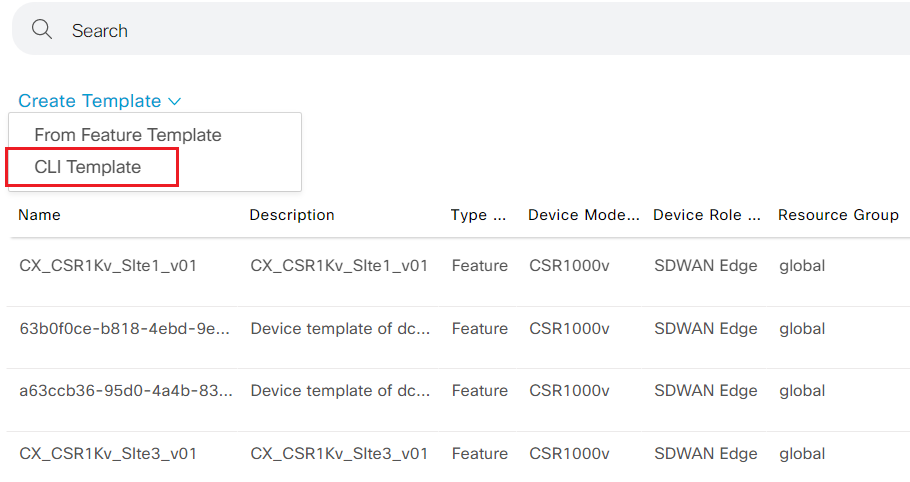
- Login vManage from https://198.18.133.200:8443. Navigate to the panel on the left and click Configuration - Templates.
- Click Create Template drop down and select CLI Template
- Step2 Select vSmart as device model and load running config from the existing vSmart as show below
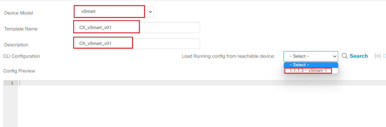 - Click Add to create the CLI device template
- Step3 Locate the newly created device template CX_vSmart_v01. Click ... and select attach devices.
- Select vSmart-1 from panel on the left and move to the panel on the right. Attach to the CLI template.
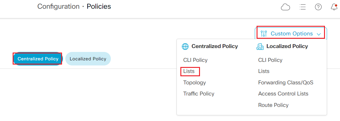
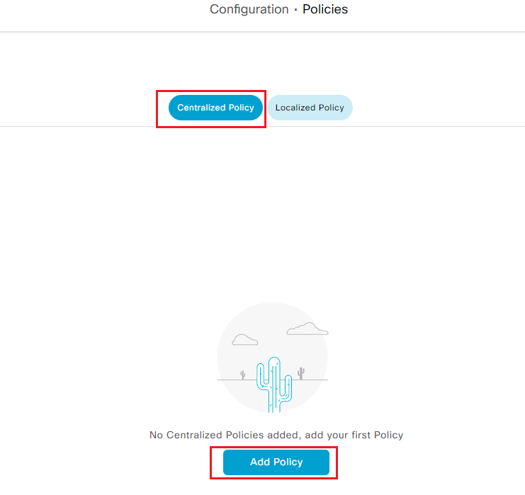
- Step4 Navigate to vManage panel on the left and click Configuration - Policies
-
Click Custom Options on the top right and select Lists under Centralized Policy
-
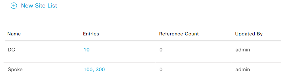
Step5 Select Site list type from the left and add New Site List
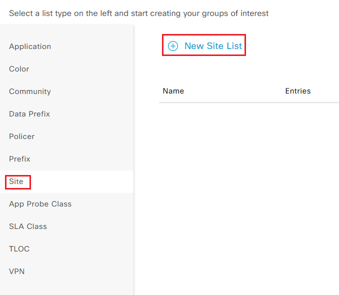
- Add site list DC with site-id 10
- Add site list Spoke with site-id 100,300
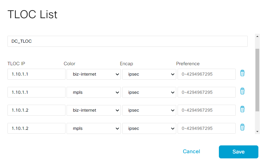
- Step6 Select TLOC list type from the left and add New TLOC List
- Add new TLOC List DC_TLOC
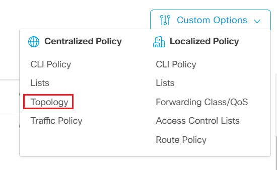
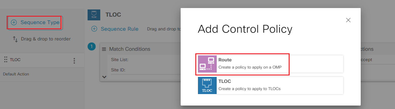
- Step7 Click Custom Options and select Topology under Centralized Policy
- Step8 Add Custom Control (Route & TLOC) under add topology drop down
- Name the new policy Hub_Spoke_v01 with description Hub_Spoke_v01
- Step9 Click Sequence Type on the left and select TLOC
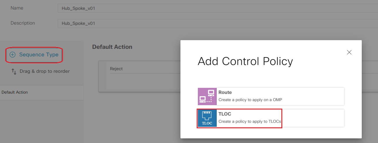
-
Select Sequence Rule to add first rule
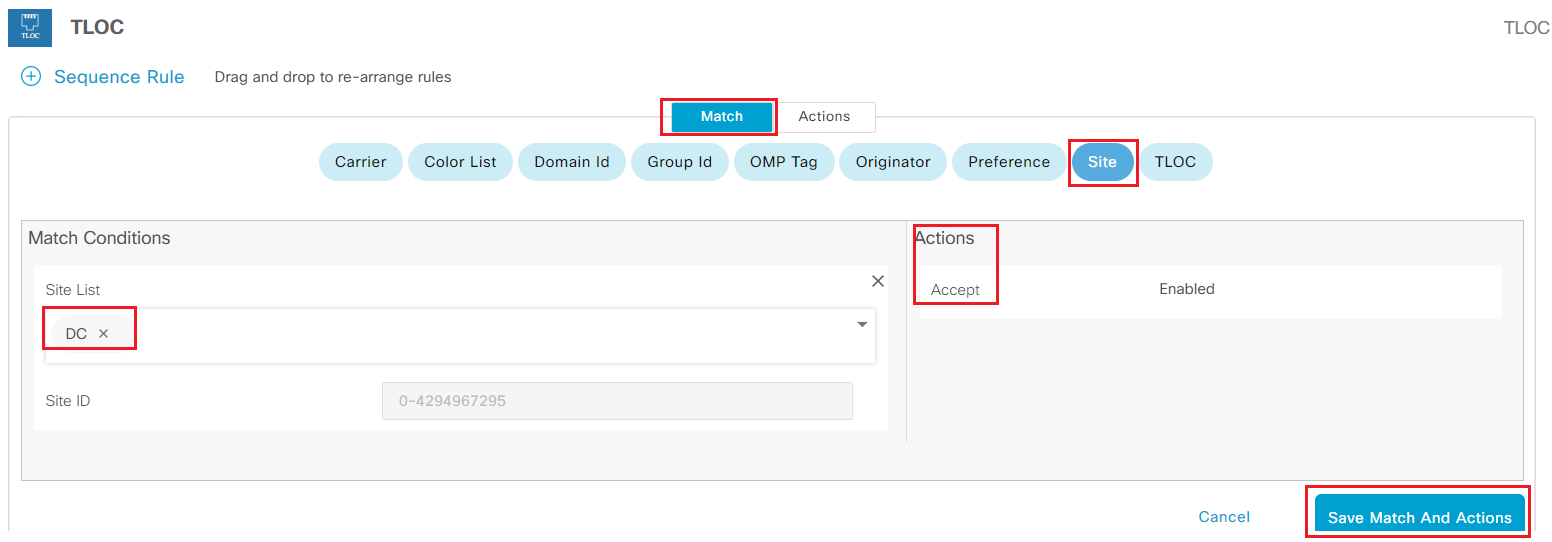
- Under Match tab
- Click Site under Match condition
- Select DC as Site List under Match Conditions
- Under Actions
- Check Accept
- Click Save Match And Actions to add this rule
-
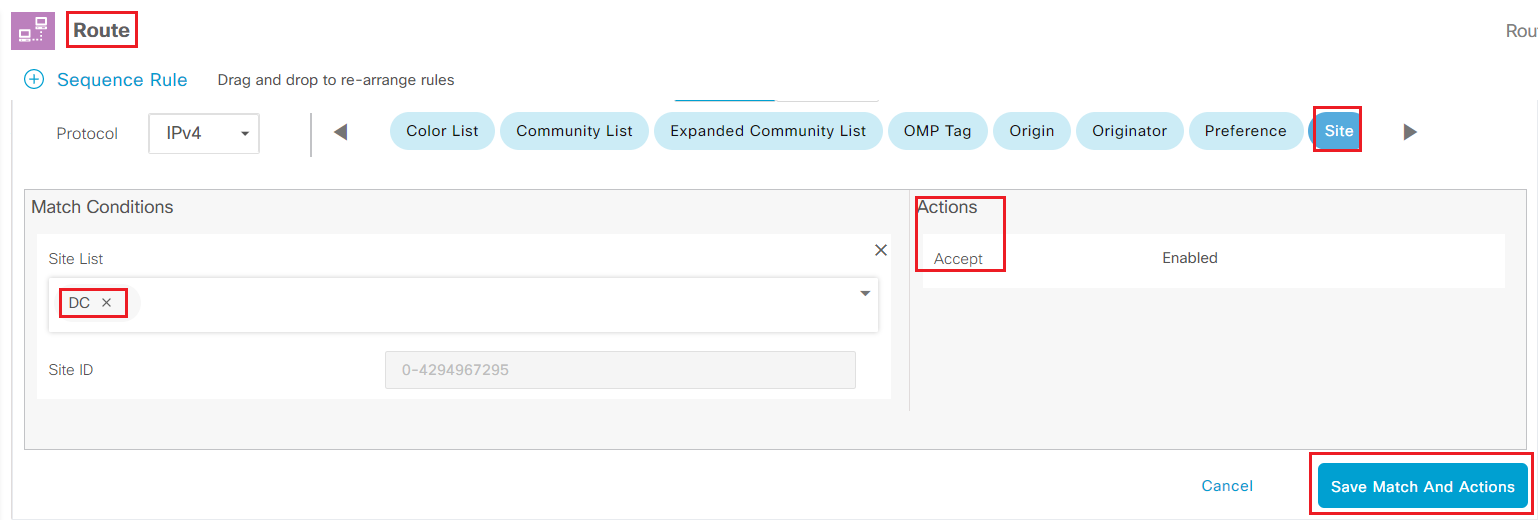
Step10 Click Sequence Type on the left and select Route
-
Select Sequence Rule to add first rule
- Under Match tab
- Click Site under Match condition
- Select DC as Site List under Match Conditions
- Under Actions
- Check Accept
- Click Save Match And Actions to add this rule
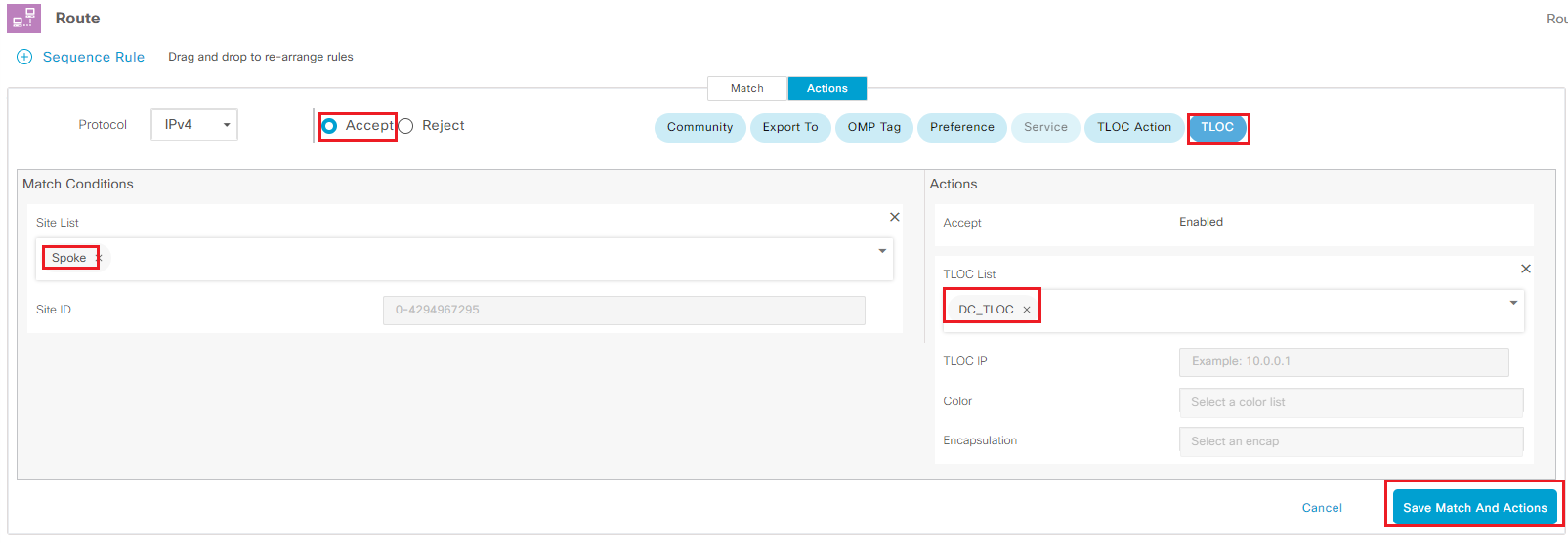
- Select Sequence Rule to add second rule
- Under Match tab
- Click Site under Match condition
- Select Spoke as Site List under Match Conditions
- Under Actions
- Check Accept, Click TLOC under Actions
- Select DC_TLOC as TLOC List
- Click Save Match And Actions to add this rule
-
Save Control Policy
-
Step11 Click Configuration - Policies and select Add Policy under Centralized Policy
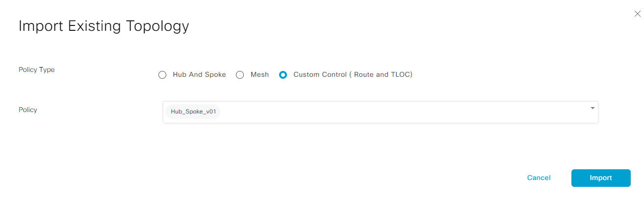
- Click Next proceed to Configure Topology and VPN Membership. Click Add topology drop down under Topology and select Import Existing Topology
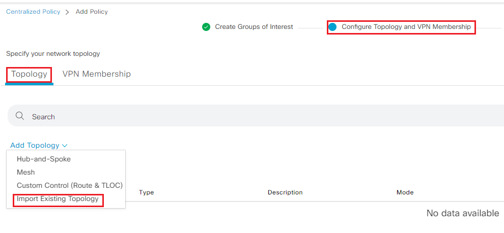
- Import Hub_Spoke_v01 policy under Customer Control policy type
- Click Next proceed to Apply Policies to Sites and VPNs
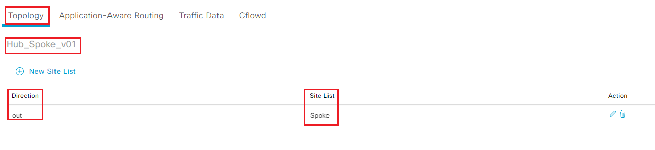
- Under Topology panel, click New Site List under Hub_Spoke_v01
-
Select Spoke under Outbound Site List and click Add
-
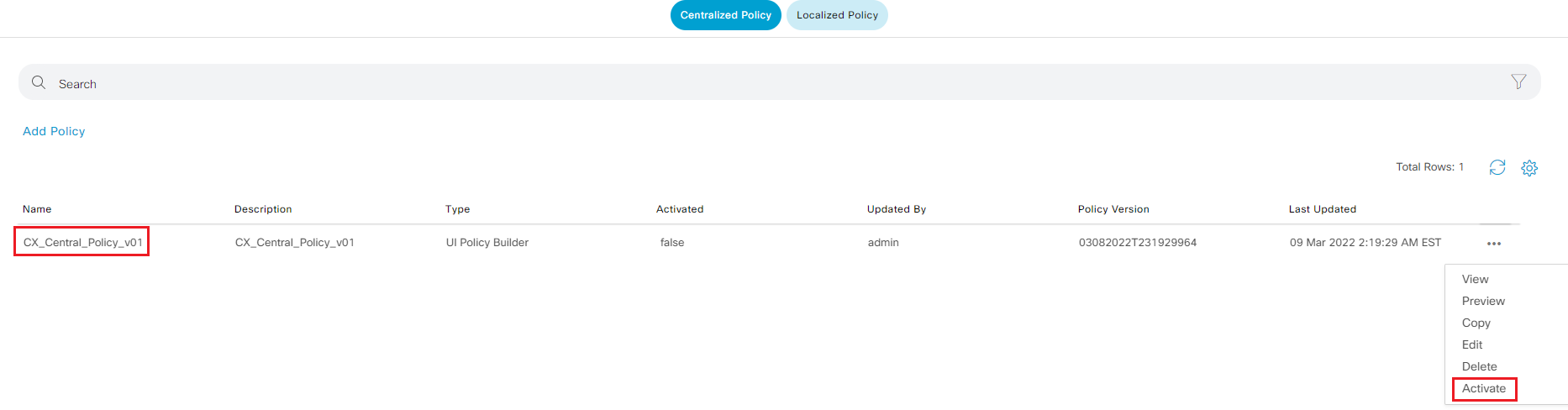
Name Policy CX_Central_Policy_V01 and click Save Policy
-
Step11 On the centralized policy page, locate the new policy, Click ... and select Activate to push the policy configuration to vSmart-1
- Step12 Login to br1-ce1 from SSH and run
show sdwan bfd sessionsto verify br1 only has tunnel to DC
 br1-ce1#show sdwan bfd sessions
                                      SOURCE TLOC      REMOTE TLOC                                      DST PUBLIC                      DST PUBLIC         DETECT      TX
SYSTEM IP        SITE ID  STATE       COLOR            COLOR            SOURCE IP                       IP                              PORT        ENCAP  MULTIPLIER  INTERVAL(msec  UPTIME          TRANSITIONS
------------------------------------------------------------------------------------------------------------------------------------------------------------------------------------------------------------------
1.10.1.1         10       up          mpls             mpls             10.1.2.2                        10.1.0.2                        12346       ipsec  7           1000           10 0:11:03:18   1
1.10.1.2         10       up          mpls             mpls             10.1.2.2                        10.1.1.2                        12346       ipsec  7           1000           10 0:11:03:17   1
1.10.1.2         10       up          biz-internet     biz-internet     19.1.3.6                        19.1.2.2                        12346       ipsec  7           1000           10 0:11:03:13   0
1.10.1.1         10       up          biz-internet     biz-internet     19.1.3.6                        19.1.23.3                       12346       ipsec  7           1000           10 0:11:03:13   0
- On the terminal, run
show ip route vrf 1to verify the next hop for br3 prefix 10.40.100.0/24 is DC Edge router.
br1-ce1#show ip route vrf 1

Routing Table: 1
Codes: L - local, C - connected, S - static, R - RIP, M - mobile, B - BGP
       D - EIGRP, EX - EIGRP external, O - OSPF, IA - OSPF inter area
       N1 - OSPF NSSA external type 1, N2 - OSPF NSSA external type 2
       E1 - OSPF external type 1, E2 - OSPF external type 2, m - OMP
       n - NAT, Ni - NAT inside, No - NAT outside, Nd - NAT DIA
       i - IS-IS, su - IS-IS summary, L1 - IS-IS level-1, L2 - IS-IS level-2
       ia - IS-IS inter area, * - candidate default, U - per-user static route
       H - NHRP, G - NHRP registered, g - NHRP registration summary
       o - ODR, P - periodic downloaded static route, l - LISP
       a - application route
       + - replicated route, % - next hop override, p - overrides from PfR
       & - replicated local route overrides by connected

Gateway of last resort is not set

      10.0.0.0/8 is variably subnetted, 8 subnets, 2 masks
m        10.1.12.0/24 [251/0] via 1.10.1.2, 11:04:50, Sdwan-system-intf
                      [251/0] via 1.10.1.1, 11:04:50, Sdwan-system-intf
m        10.10.11.0/24 [251/0] via 1.10.1.1, 11:04:50, Sdwan-system-intf
m        10.10.12.0/24 [251/0] via 1.10.1.2, 11:04:50, Sdwan-system-intf
m        10.10.100.0/24 [251/0] via 1.10.1.2, 11:04:50, Sdwan-system-intf
                        [251/0] via 1.10.1.1, 11:04:50, Sdwan-system-intf
m        10.30.100.0/24 [251/0] via 1.10.1.2, 11:04:50, Sdwan-system-intf
                        [251/0] via 1.10.1.1, 11:04:50, Sdwan-system-intf
m        10.40.100.0/24 [251/0] via 1.10.1.2, 00:02:54, Sdwan-system-intf
                        [251/0] via 1.10.1.1, 00:02:54, Sdwan-system-intf
C        10.200.100.0/24 is directly connected, GigabitEthernet4
L        10.200.100.3/32 is directly connected, GigabitEthernet4
CONFIGURATION! You have completed the lab! Here are the tasks you learned today
- Manually onboard a wan edge router with minimal config.
- Migrate a legacy site to sdwan site
- Build topology for tloc-ext to improve site redundancy
- Use centralized policy to build hub and spoke topology